|
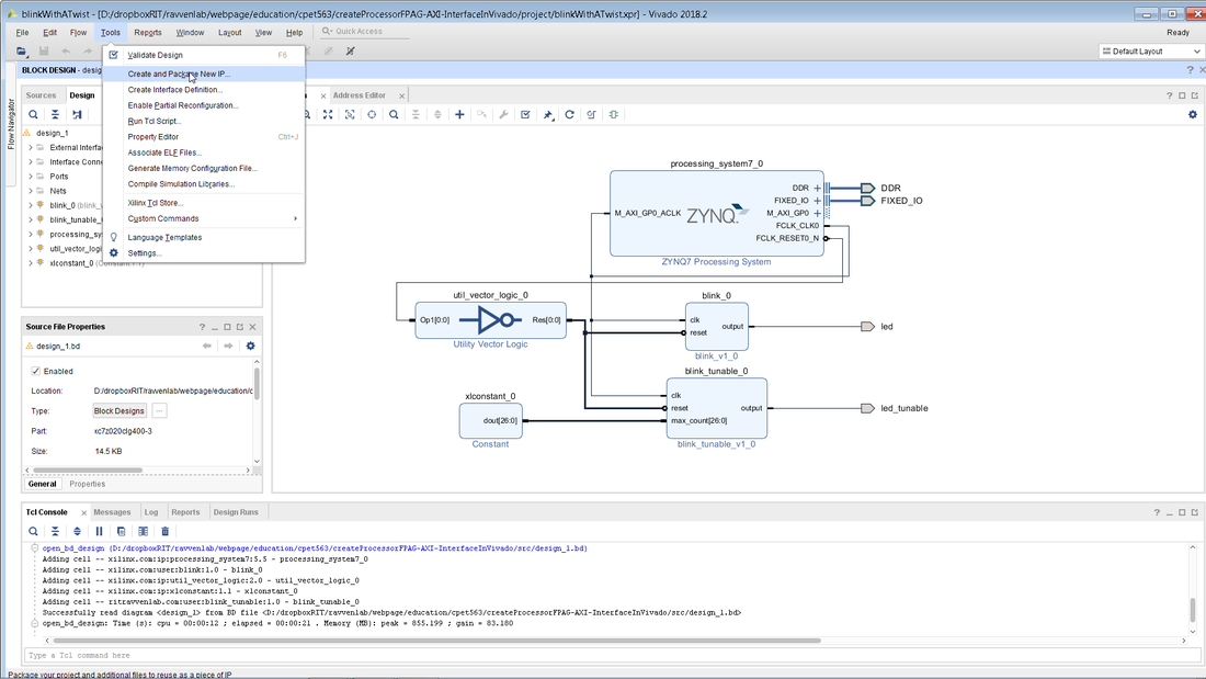
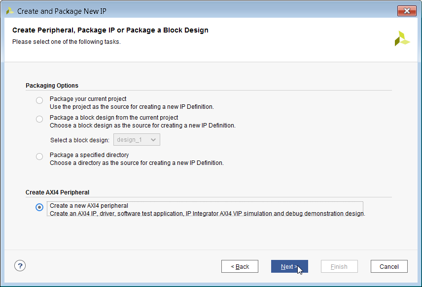
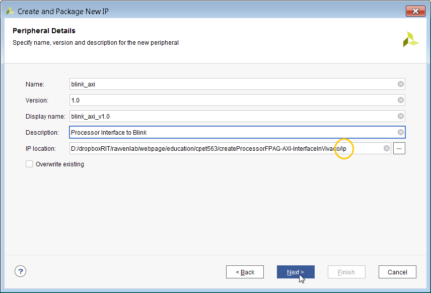
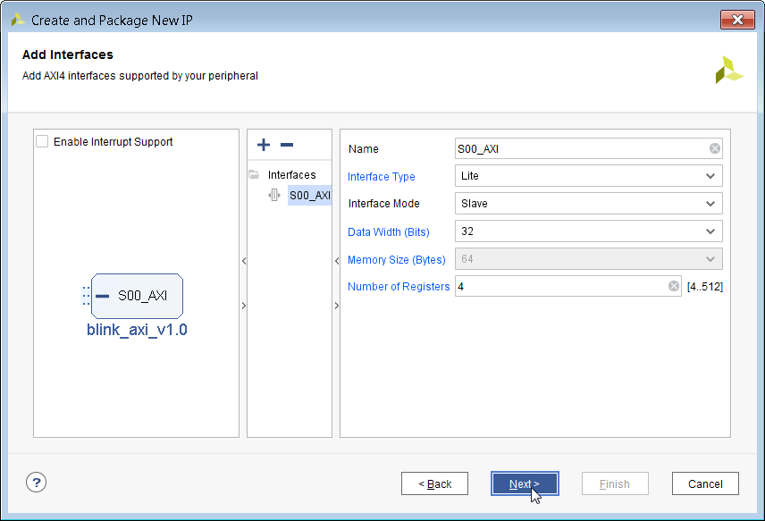
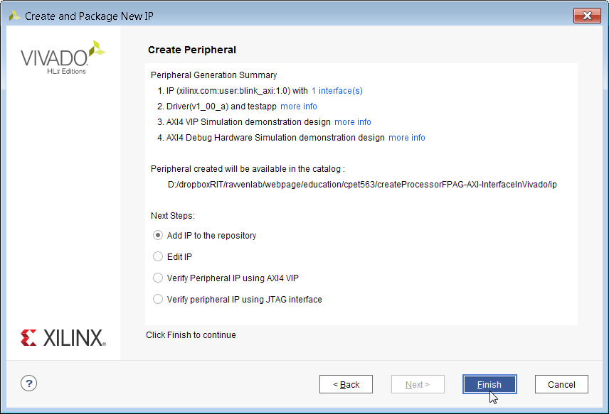
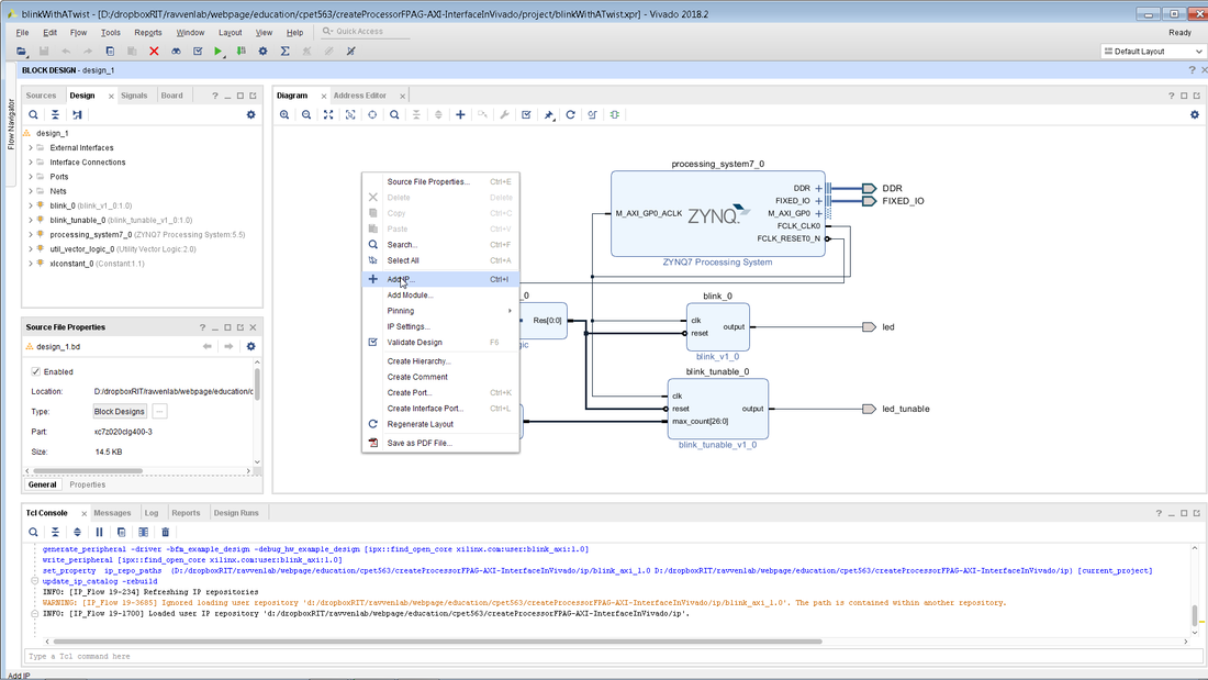
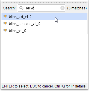
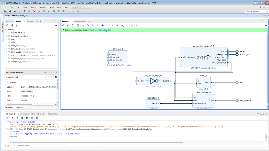
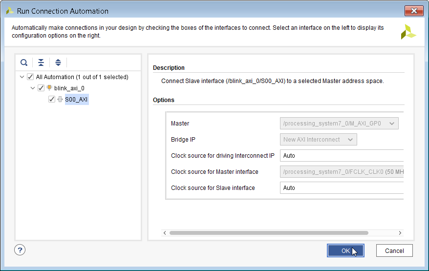
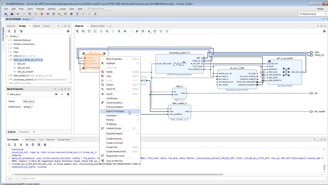
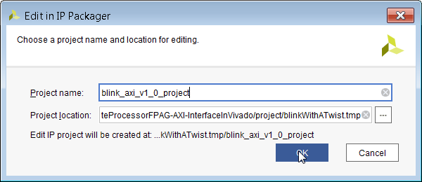
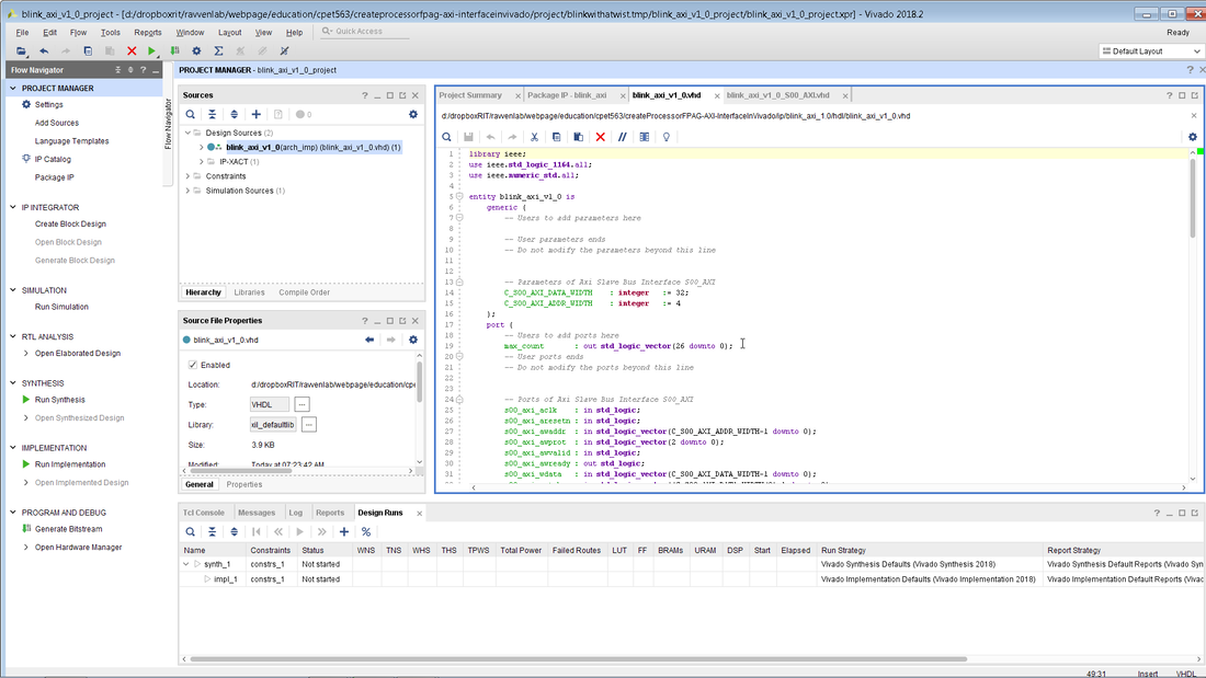
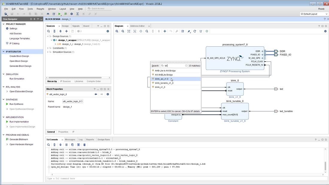
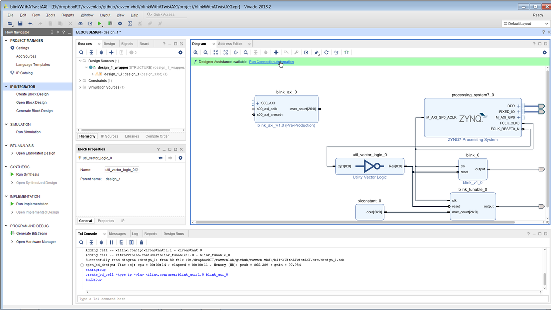
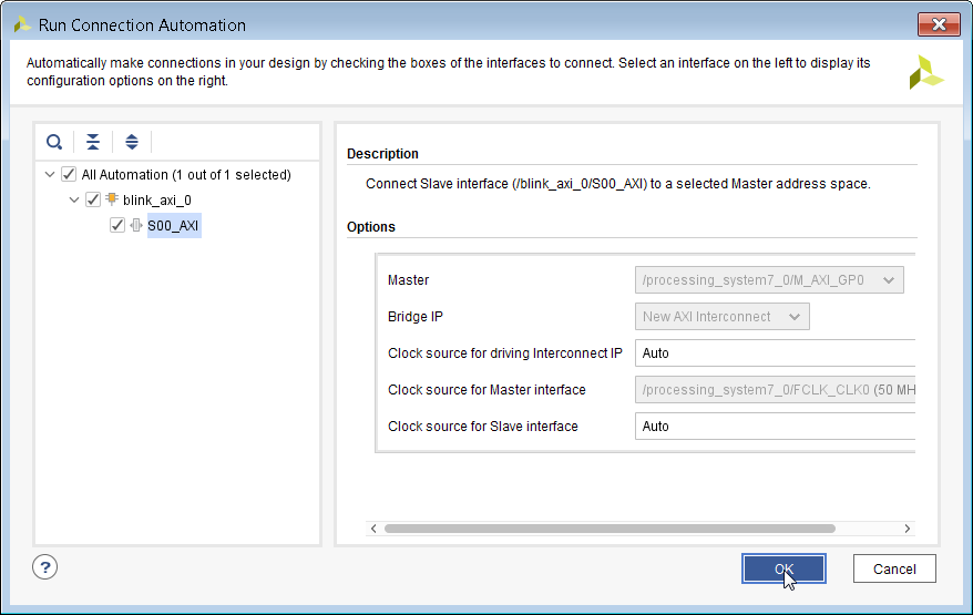
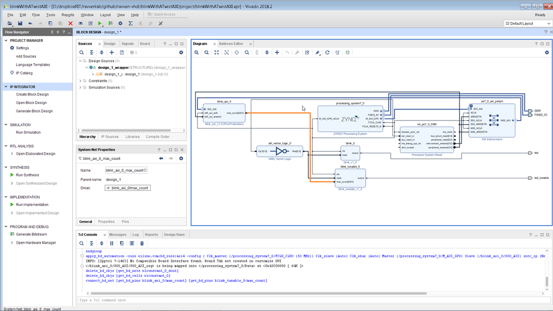
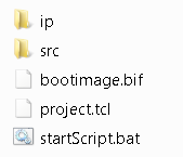
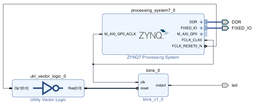
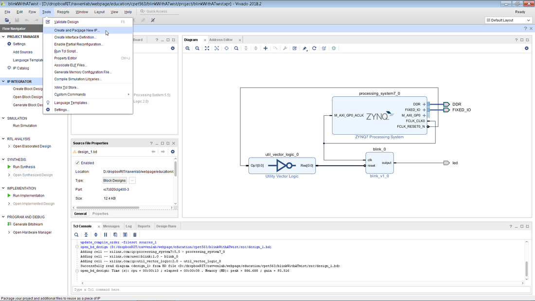
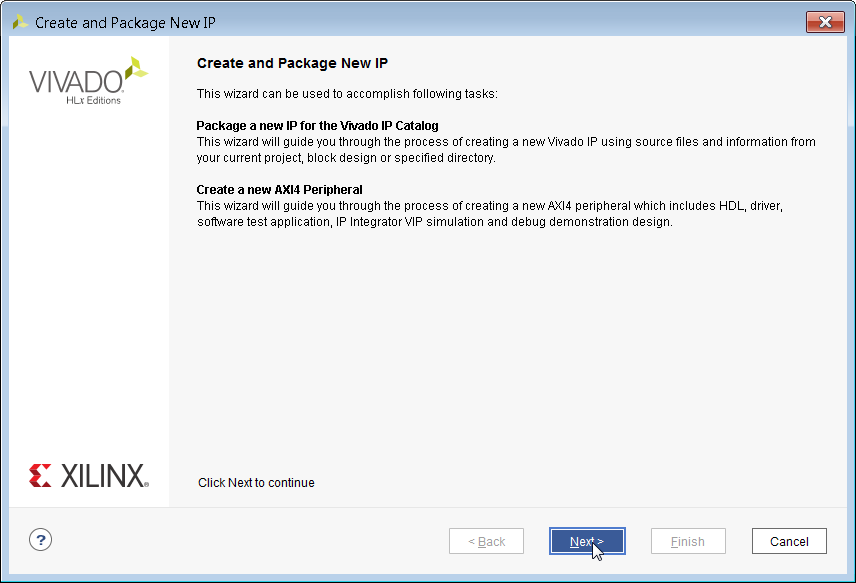
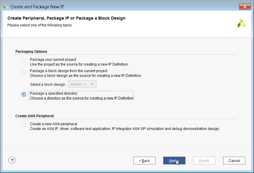
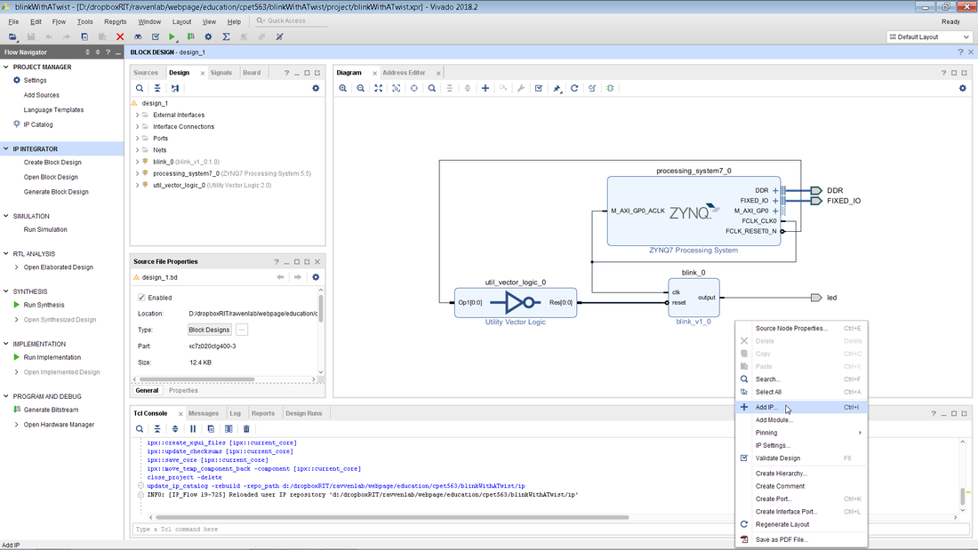
In this blog, the blinkWithATwist code is modified so that the blink rate can be controlled via the processor. Pull down the code, click on startScript.bat within the blinkWithATwist folder to create the project, and then open it up in Vivado. Note that the end result of this blog [blinkWithATwistAXI] is also in the repo, but if you want to work though the blog you should use blinkWithATwist as your starting point. You should see something like the block diagram below. This is the exact same project that was covered in the Blink With a Twist blog post. Once you have opened up the block diagram as shown below, click on the Tools menu and then Create and Package New IP. Instead of packaging a specific directory as we did in a previous post, we will be creating a new AXI peripheral. Select the bottom radio button and click Next. In this step you need to enter the name and description of your new IP block. Make sure to use something meaningful instead of things like MyIP. Note that you must specify the IP folder that you are using via your scripting utopia framework. If you do not modify this path to point to ip, it will point to ip_repo by default. For this processor link we will be using the simplest AXI interface which is AXI Lite. Keep all of the default settings and click Next. Click on Next to finish up the IP creation. In the block diagram, right-click to open up the Add IP option and select blink_axi_v1.0 as shown below. Once your IP has been added to the block diagram you can click on Run Connection Automation to automatically setup the AXI port signals. Click OK. Technically we have created a processor/FPGA link however the only ins and outs of the AXI block are the AXI interface signals. In order to control the tunable blink we want to replace the constant for max_count with a value that comes from the processor. The only way that this can be done is by modifying the newly created blink_axi block. This can be done by right-clicking the block and selecting Edit in IP Packager. A temporary IP project will be created and the name and location don't really matter here. Just click on OK. You will need to modify the two files that makeup the blink_axi IP block. The two modified file can be found below. I recommend downloading these two files and just copying their entire contents into the existing files. Note that you will have to make sure that you have named your IP exactly as I have in the tutorial. Another option would be to do a 'diff' on these two files against the existing IP files and manually copy over the added lines of code.
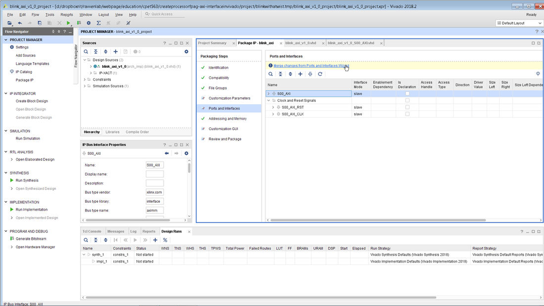
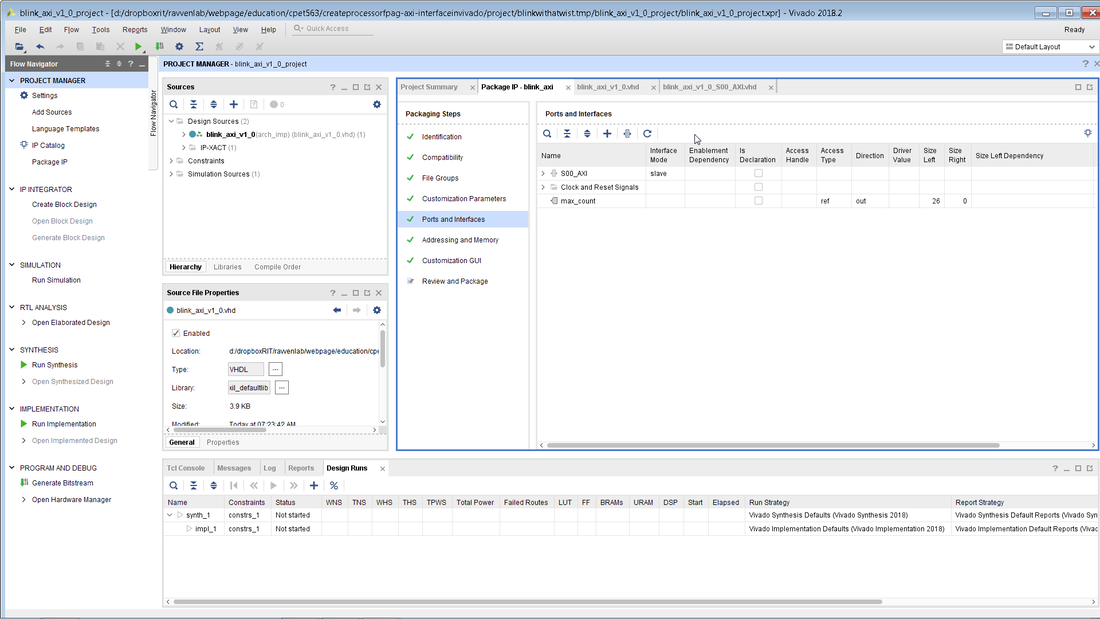
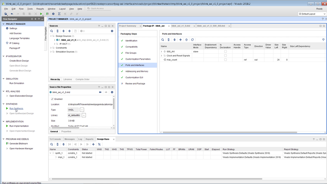
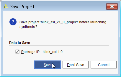
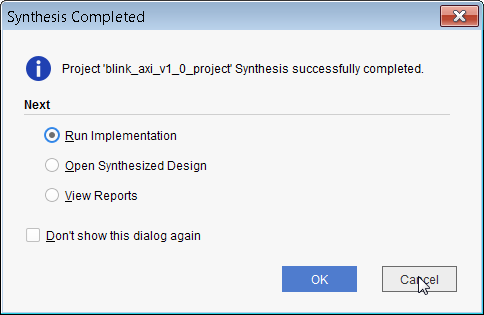
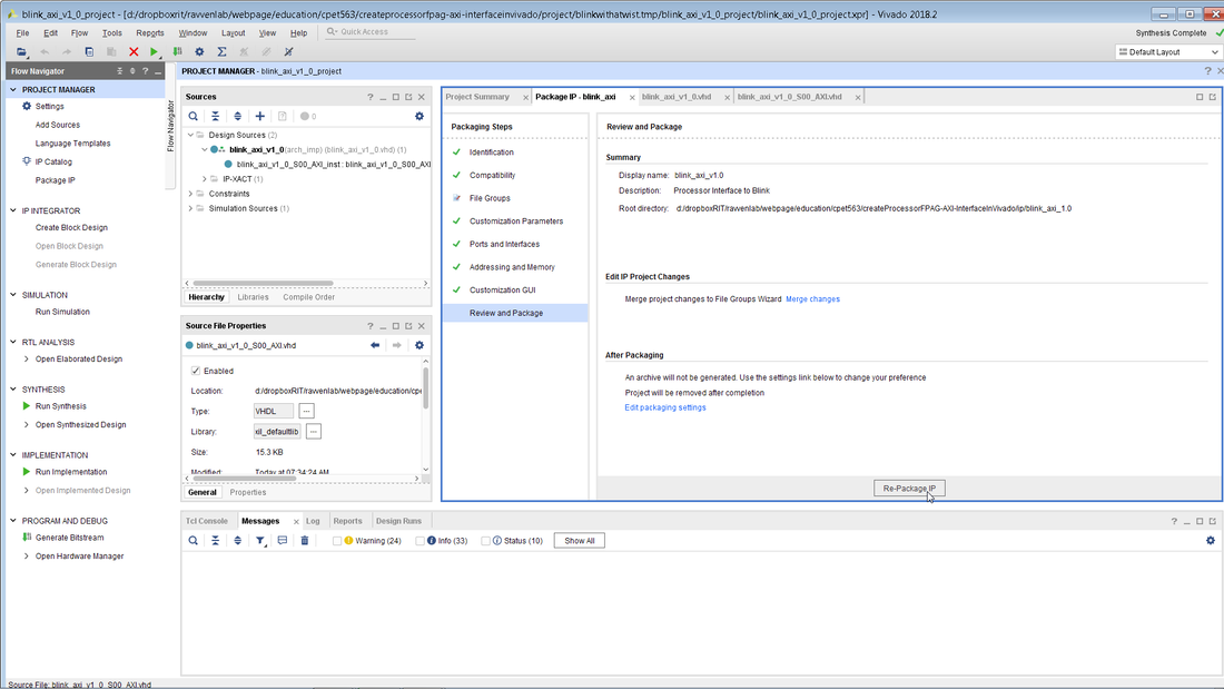
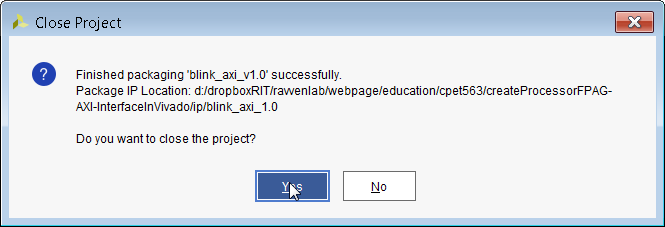
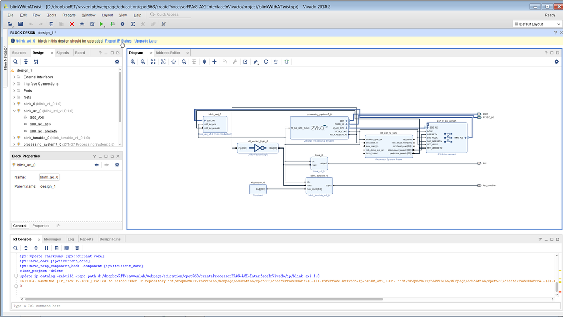
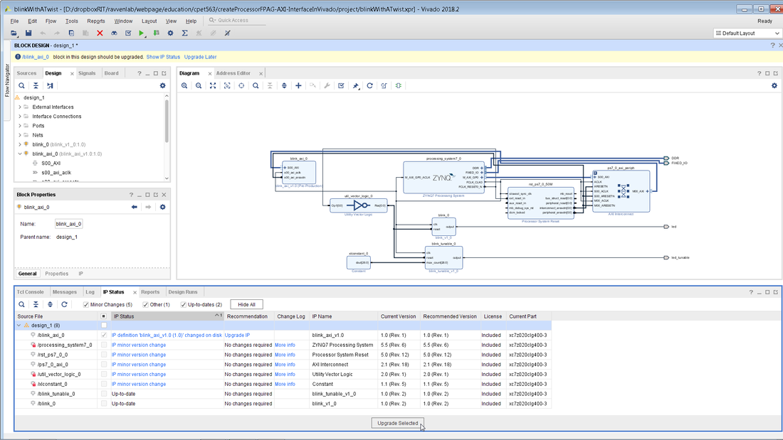
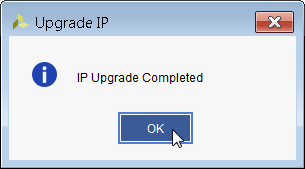
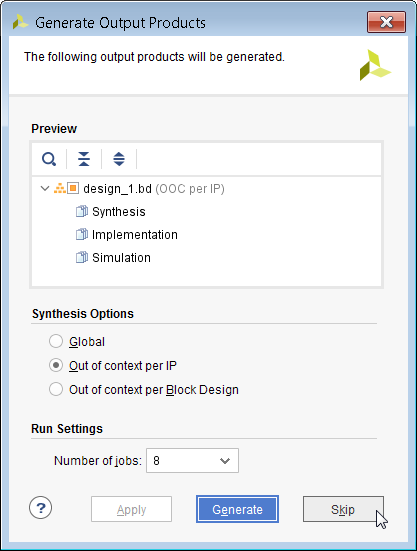
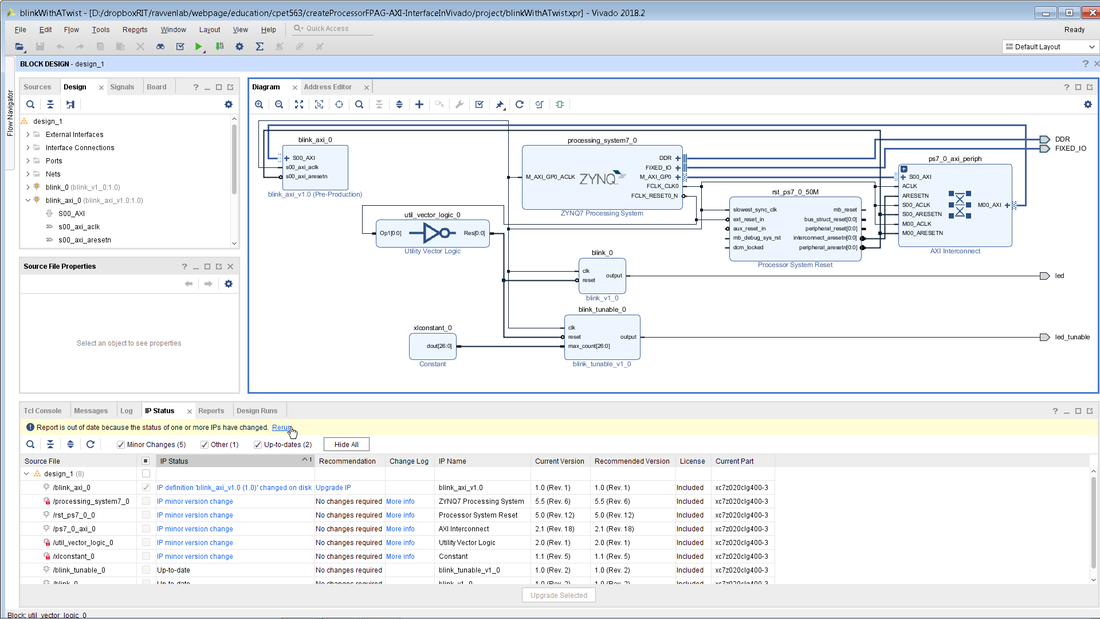
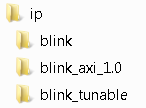
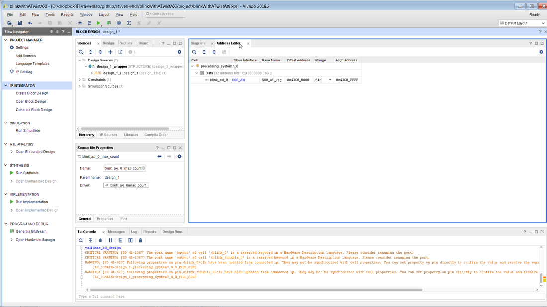
Once the two files have been modified, you must ensure that you select the various packaging steps on the left and click on the Merge changes text in blue. As you can see below my max_count signal does not appear in the ports list until the Merge changes text is clicked. Remember to always click on Run Synthesis before you formally package the IP. This will save you time in the long run as you don't want to find that you forgot a semicolon in your blink module at the end of a 1 hour full project compilation process. Clicking on the Run Synthesis text might ask you to save the project and just click Save. When synthesis has completed successfully just click on Cancel. Finally package the IP and close the project. The next couple of steps are quite vexing as I believe there is a bug in Vivado here. Notice how the max_count signal is not coming out of our newly edited IP block. This is supposed to be remedied by updating the IP which is done by licking on Report IP Status and then on Upgrade Selected as shown below. Once the IP is upgraded you can chose to either generate or skip the output projects. I typically skip this part. The strange Vivado bug sill manifests itself even when I choose to generate the output products. Even after updating the blink_axi IP there is still no max_count coming out of it. You can try to click on Rerun in order to update the IP again but I believe there is something wrong going on here. By taking a step back we can find a nice solution to this apparent bug. The whole goal of this blog was to generate the AXI link IP and we have successfully done that. Why not save off that IP folder and start fresh with the blinkWithATwist project. All you need to do is pull down a fresh blinkWithATwist directory and add the blink_axi_1.0 IP into its IP folder. The two files that we edited before should be located within the blink_axi_1.0 folder. When you run the startScript.bat file in the blinkWithATwist folder and open up Vivado you should see a block diagram just like you did at the start of this tutorial. The only difference is that now when you right-click you will see your newly created blink_axi_v1.0 IP come up. Select that IP block in order to add it to your design. Notice how the max_count is now coming out of the IP block. We did not change any code in the IP block but simply blew away the old project and started fresh. Click on the Run Connection Automation in order to link up the AXI interface signals as was done above. Next, delete the constant block that is feeding the blink_tunable block and route the max_count signal from the blink_axi block to the blink_tunable block. This effectively links up the processor to the FPGA tunable blink routine. The last step is to click on the Address Editor and to expand the tabs in order to see the hex address of 0x43c0000 which is the base address of the AXI link that was created. We will demonstrate how to use that base address to toggle the blnk frequency in a future post. Once you have connected up your block diagram, make sure to save everything, exit out of Vivado, blow away the bloatware files, update the scripting utopia compile flag to 1, and then click on startScript.bat. This will generate the system.bit as well as system.bit.bin files for you. Congratulations you are now ready to control blink from the processor. If you want just grab all the source files for this blog post, just go here and clone or download the repo. The completed files are located in the blinkWithATwistAXI folder.
0 Comments
One of the problems with copying the system.bit file to the SD card for a firmware change is that one has to take the SD card out of the Snickerdoodle and load it into a PC. This is fine once or twice but it can get very frustrating when you are making many firmware updates.. especially late at night. A better way is to purchase a Breaky Breaky and a JTAG programming cable from Digilent like the one shown below and program the FPGA via JTAG. JTAG not only allows for programming without taking the SD card out of the Snickerdoodle but one can also perform real-time debugging of the FPGA with logic viewers and advanced triggering.
To setup the root password type:
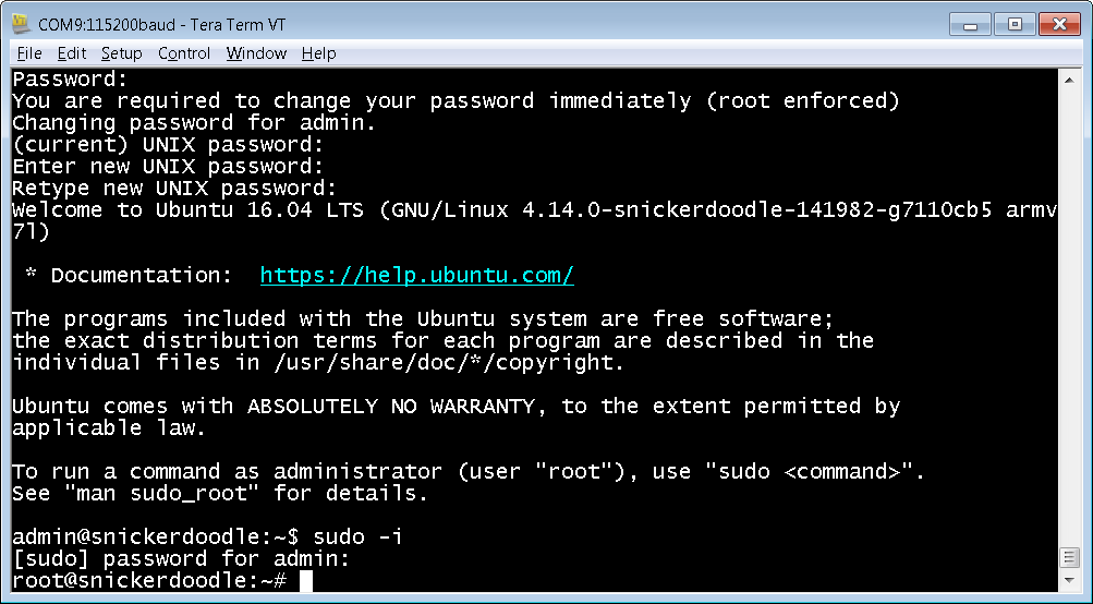
sudo -i then type snickerdoodle123 to get to root then type passwd enter the new password The best way to transfer files between your Snickerdoodle and your PC is to setup a Samba file share on the Snickerdoodle that can be accessed via your PC. To do this a couple packages must be downloaded via the Linux prompt. Log into the Snickerdoodle and perform a 'sudo -i' to attain super user privileges. Then type:
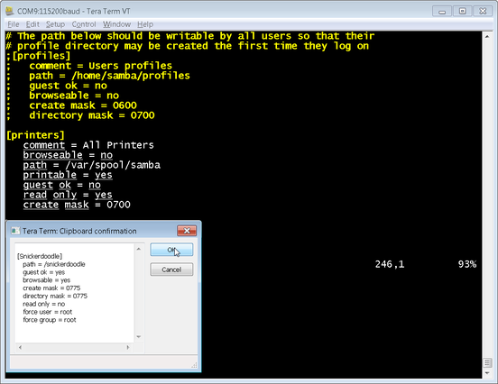
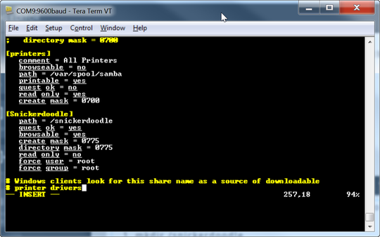
[Snickerdoodle] path = /snickerdoodle guest ok = yes browsable = yes create mask = 0775 directory mask = 0775 read only = no force user = root force group = root Once you are in the file, scroll down to the section called printers and enter the below commands
Save the file by typing
Once you have saved the file, enter the below three lines at the command prompt:
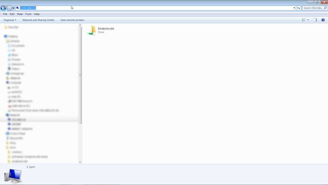
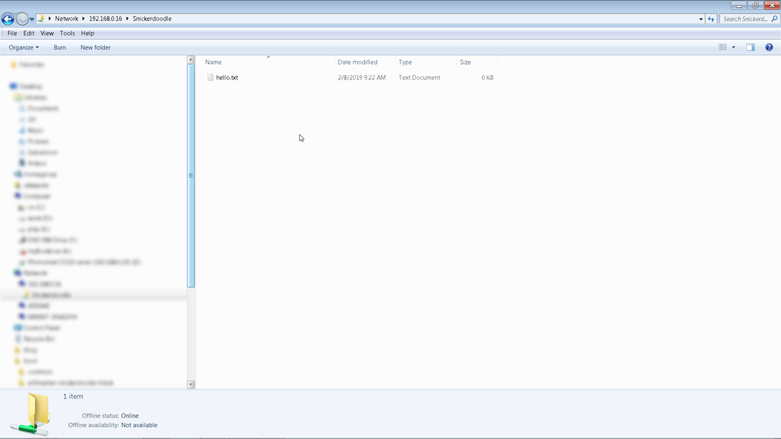
Open up a Windows Explorer window and type \\xxx.xxx.xxx.xxx where the x's represent the Snickerdoodle IP address. For me it would be \\192.168.0.16 Once you enter the Snickerdoodle IP address you should see the contents of the /snickerdoodle folder which was the hello.txt file Congratulations you not have Snickerdoodle file sharing up and running!
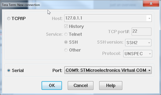
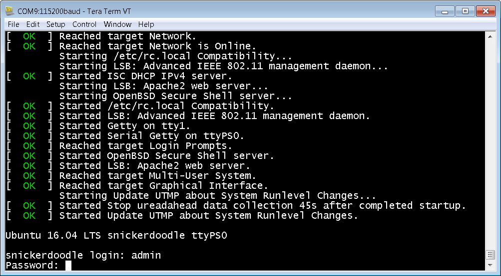
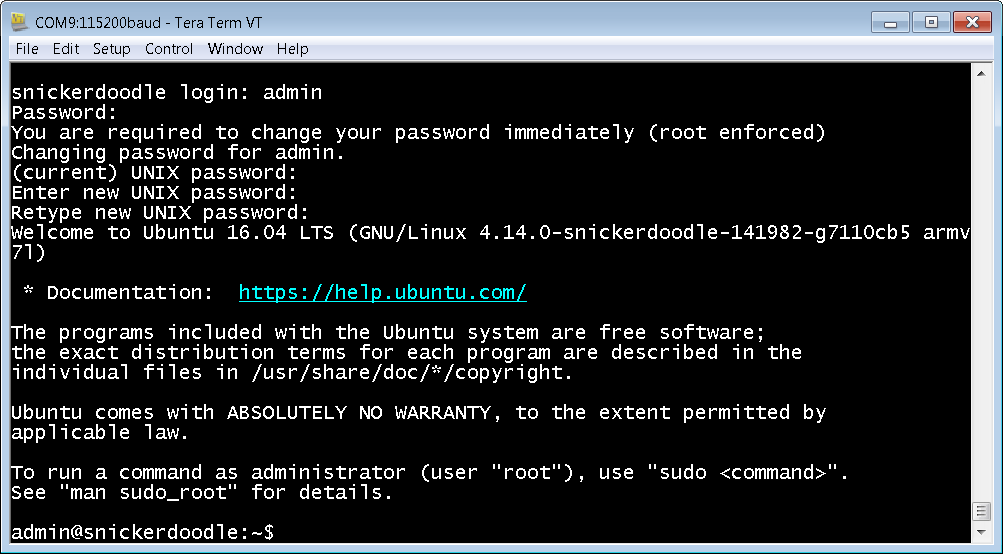
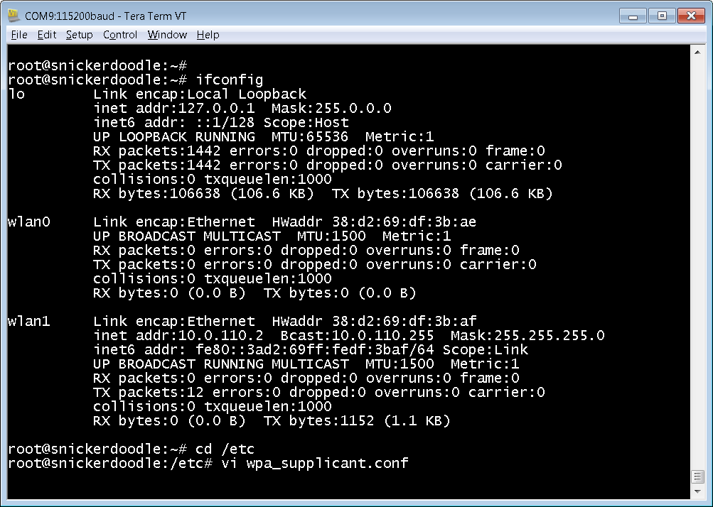
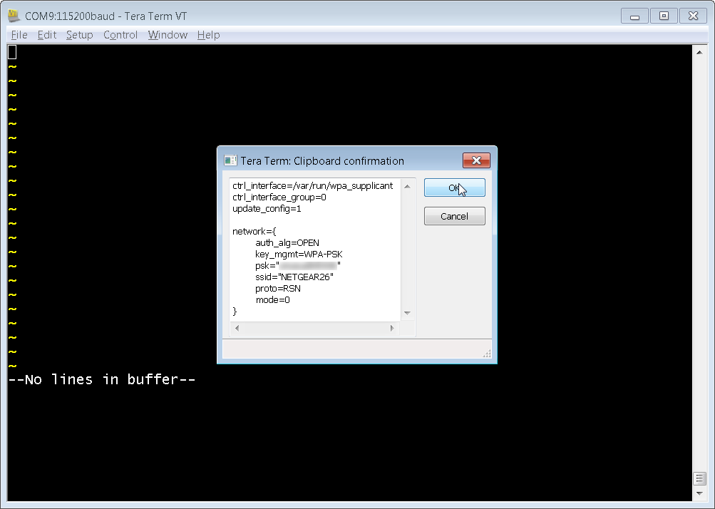
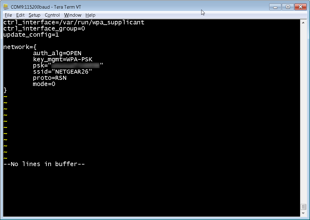
The next couple blog posts are about configuring Linux on the Snickerdoodle. In order to do so, one must be able to communicate with the board via the USB port. You will need to download the STM USB-UART driver here before the Snickerdoodle is recognized by your computer. You will also need to download a terminal program such as Putty or TeraTerm. Once you have downloaded the UART driver an a terminal program, power on the Snickerdoodle by connecting it to the PC via the USB cable. After powering on, open up Tera Term, click the "Serial" option and select the STMicroelectronics Virtual Com Port. If you do not see the port you might have to unplug the Snickerdoodle, close Tera Term, and try it again. Make sure that you have a properly configured SD card installed in the system. To login use: username: admin password: snickerdoodle The next step is to get super user privileges by typing 'sudo -i' and then your new password. Once you are in the vi editor you will need to type the below commands exactly to delete all lines in the file and to set it up for pasting from the clipboard
After typing in your network credentials, save them by typing:
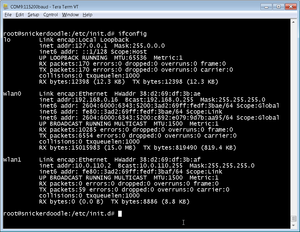
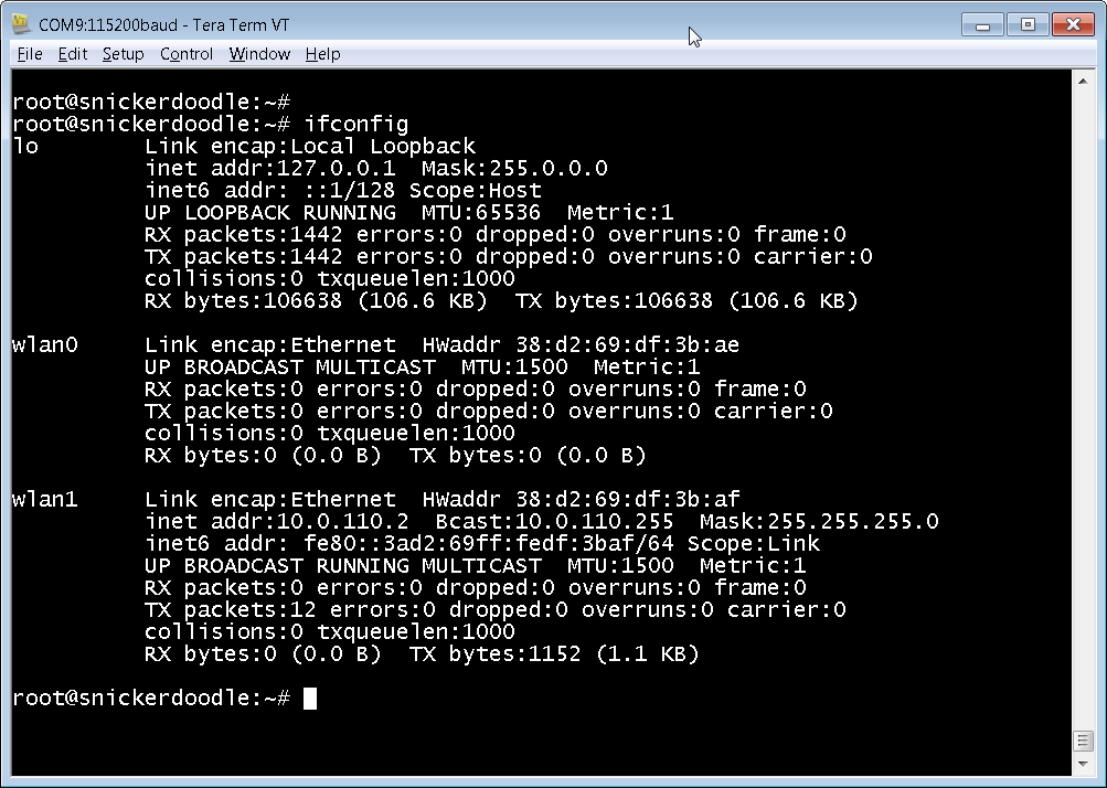
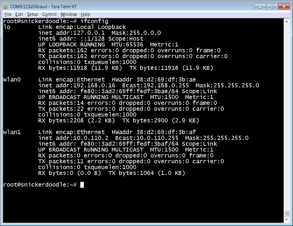
After the system reboots, login as usual and then type ifconfig. You should see that you now have an IP address for wlan0. Note that if you are on campus you might have to have your Snickerdoodle registered on the network by sending the HWaddr number to your system administrator. Congratulations, your Snickerdoodle is now online!
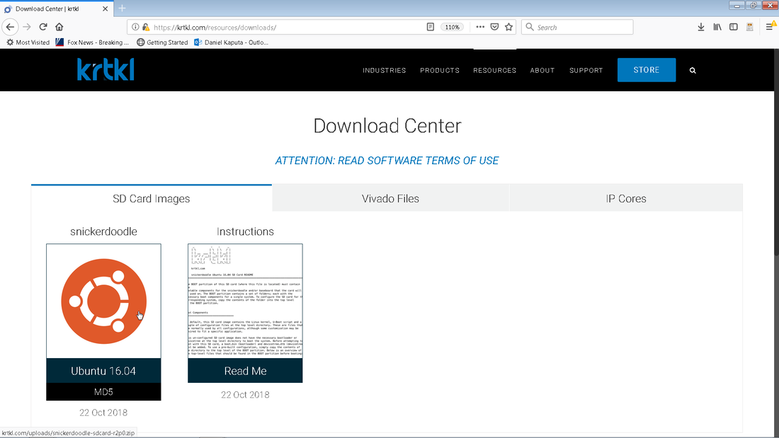
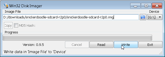
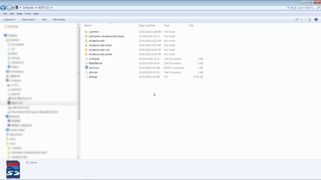
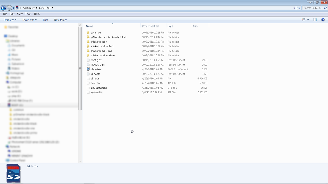
The first thing you must do in order to setup your Snickerdoodle SD card is to pull down a disk imager utility such as win32 Disk Imager. The next step is to pull down the Snickerdoodle Ubuntu 16.04 SD Card Image from here. Once you unzip the image then copy it onto a blank SD card by use of the win32 Disk Imager by selecting the .img file and clicking "Write. Once the image is finished writing you should be able to browse to the boot sector of the SD card via windows explorer and see the below files. Explaining what all of these files are is beyond the scope of this tutorial. There are two steps however that need to be taken in order to boot with your specified FPGA .bit file.
It is ok if you don't have a system.bit yet as that is only need to program the FPGA portion of the Zynq chip. You should now be able to boot up Linux and start Snickerdoodling!
By now you have probably fallen in love with the scripting utopia process, but what is the best way to create a project that has multiple IP modules? This post will walk you though modifying our blink routine so that the blink frequency can be tuned via an input port in real time. We will create a new project that has both the old blink IP block as well as the new blink IP block instantiated within them. After completing this tutorial you should be on your way to creating complicated projects that have many IP blocks in them.
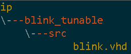
Your new folder structure should look something like this. All that you have effectively done is to copy the sample blink project, put it at the top level of the directory structure, and re-point it to the blink IP. You should be able to click on startScript.bat to kick of the script which creates the Xilinx project. Once created you can go into the project folder and open the Vivado project to see something like the image below. Congratulations, you have just make your first hierarchical IP project. The next steps are to create our new tunable blink IP block and add it to the project. There are two distict ways to add some new IP to our blinkWithATwist project
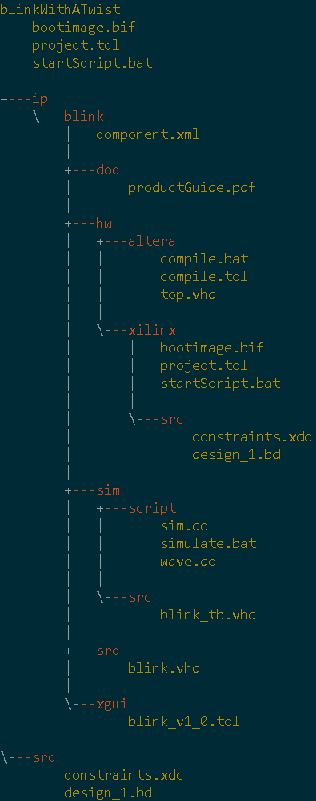
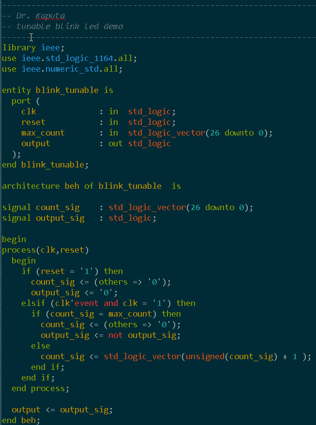
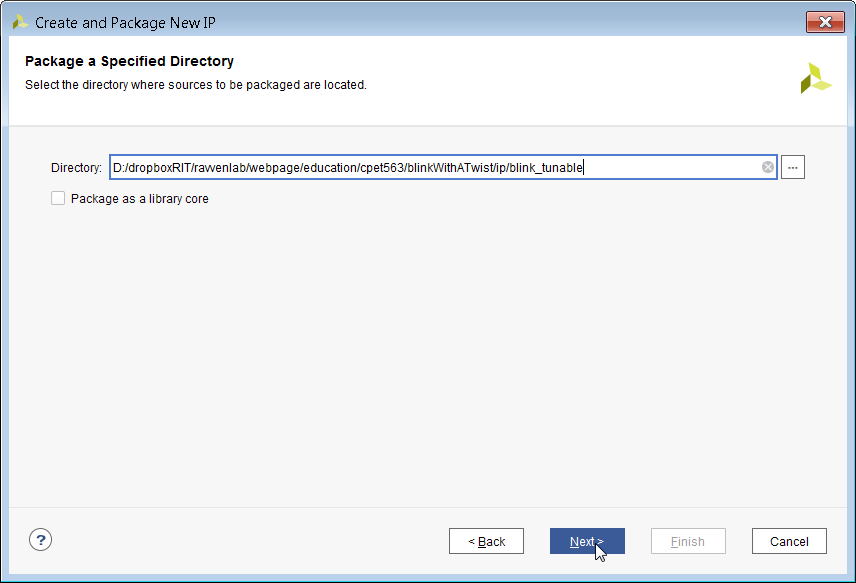
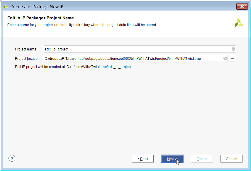
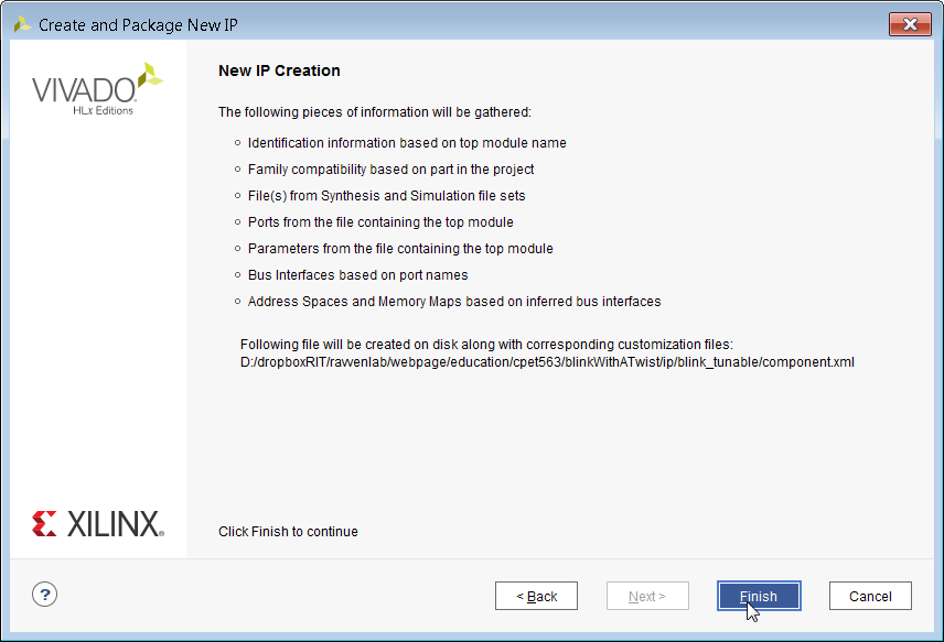
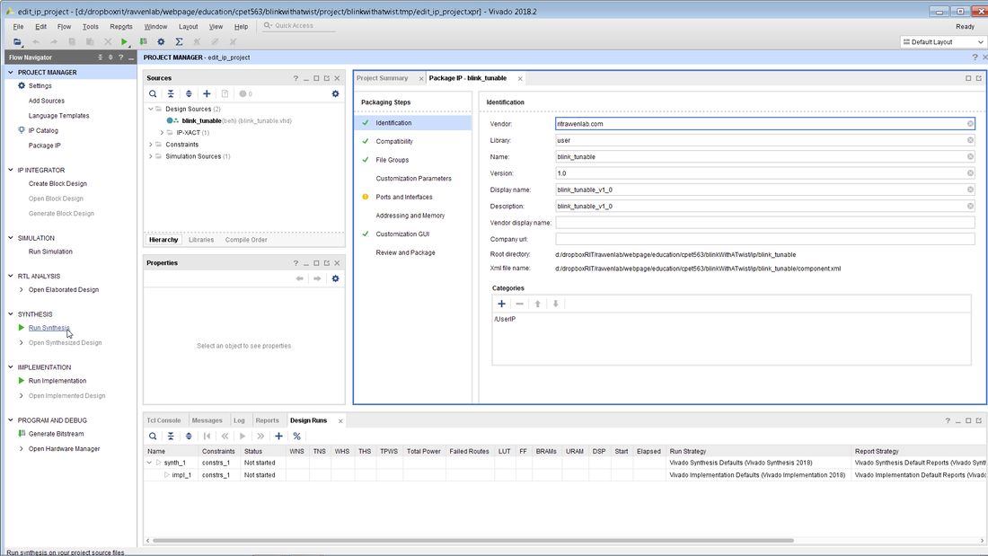
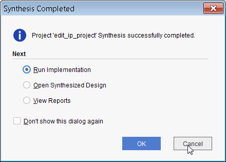
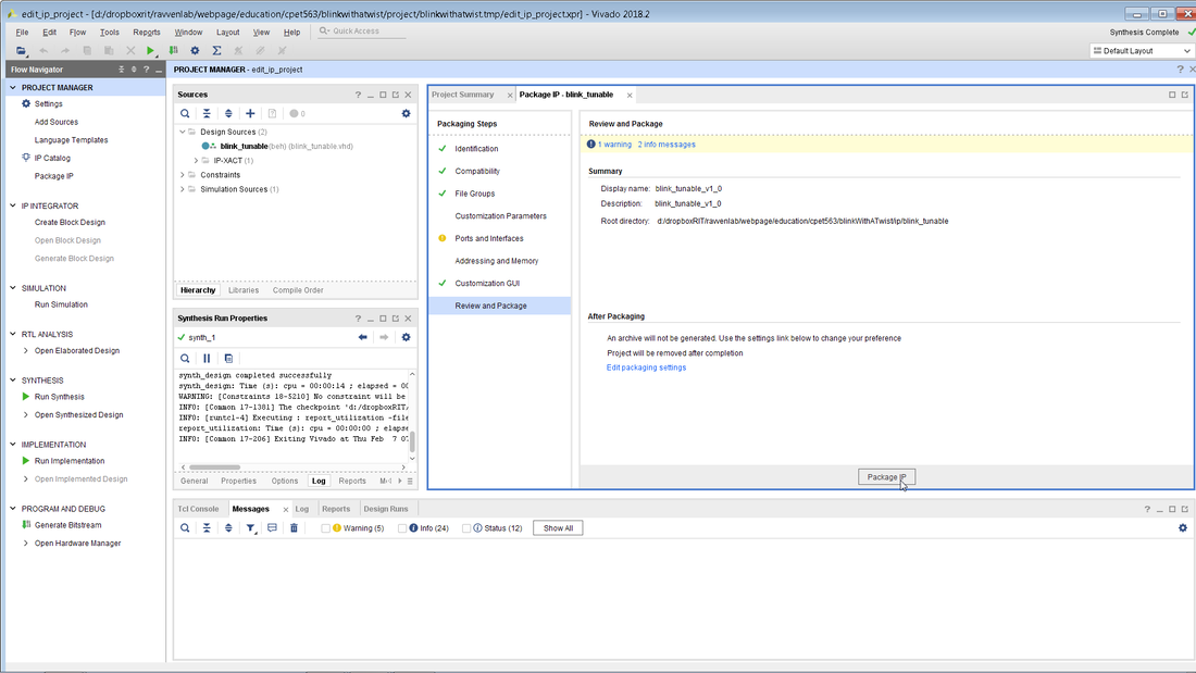
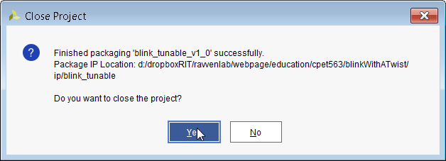
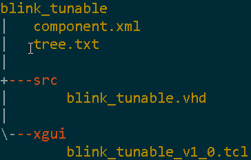
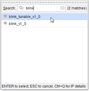
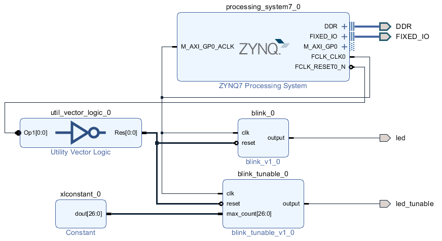
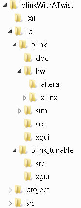
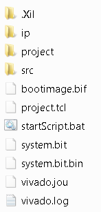
This file allows for a 1 Hz blink since 2^27 is 134,217,728 for max_count and we have a 100 MHz clock. After loading up the existing project that we copied to the top level folder, go to Tools and select Create and Package New IP. Click on Next. We will be packaging the contents of the newly created blink_tunable directory. Navigate to the folder where your blink_tunable code is. Notice how mine is located in the IP folder that we created in an earlier step. Click on Next as fast as you can for the next couple of screens. Perform a synthesis on your new IP to make sure there are no syntax errors in it. I also typically rename the vendor to something other than Xilinx. When synthesis completes successfully you can just cancel the pop-up window. Click on Package IP. Close out of the temporary IP editing project. This will bring you back to the main project. Right-clink in the block diagram and add the newly created blink_tunable IP. Connect it up as shown below. You will have to add a constant block and create an output port called led_tunable. I put a value of 100000000 into my constant which should effectively blink the LED at around 1 Hz [given a 100 MHz clock]. You will also have to update the constraints file [at the top level] to route the led_tunable signal to the proper FPGA pin. After updating the constraints file make sure to set the compile flag in the project.tcl to '1' and click on startScript.bat. After grabbing some coffee you should see the below file structures nicely generated. The left hand side shows the folder breakdown underneath the blinkWithATwist project folder and the right side shows the specific files that are found in the top level directory. The full blinkWithATwist project can be downloaded here. You can now either:
It is also recommended to go back and to flesh out the blink_tunable folder structure so that it matches the blink folder structure by adding the sim, doc, and hw folders to it. The easiest way to create the example Vivado project within the blink_tunable/hw/xilinx folder would be to:
|
||||||||||||||||||||||||
AUGMENTED REALITY - ARTIFICIAL INTELLIGENCE - VIRTUAL REALITY - UNMANNED AERIAL VEHICLE - EMBEDDED VISION

