|
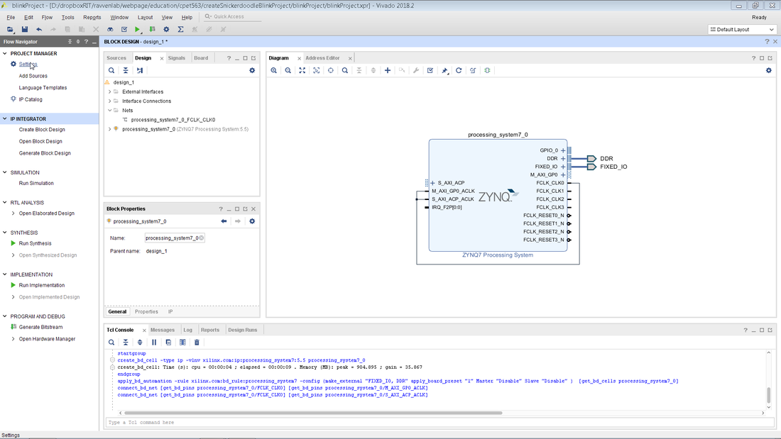
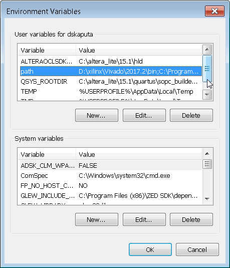
If you just went through the last blog post about creating a Vivado project you are probably exhausted. Thankfully there is a much easier way to develop your VHDL code via a scripting methodology. This post will perform the exact same task as the previous post but with only the click of a single button. There are a couple steps that one needs to take however in order to setup the scripting environment. The first step is to make sure that the correct version of Vivado is listed on the system path. On Windows 7 you will need to open up the system properties window and then click on environment variables. 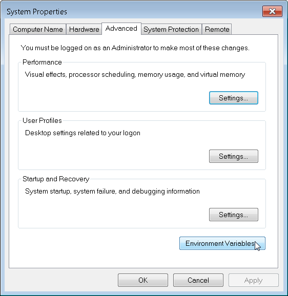 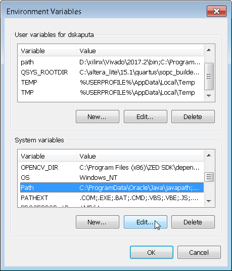 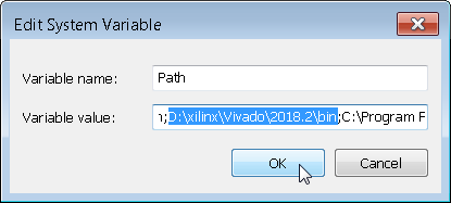  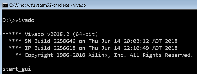 
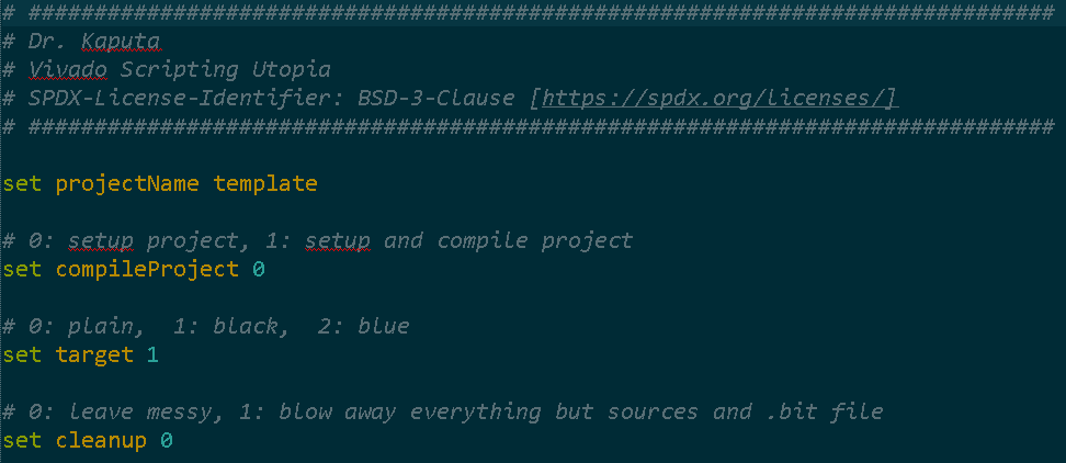
It is important to note that the script file has four main options that can be set by the user.
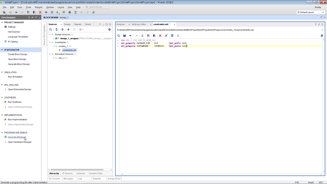
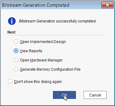
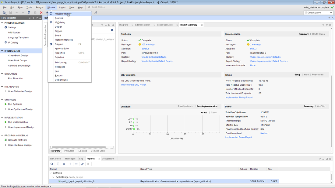
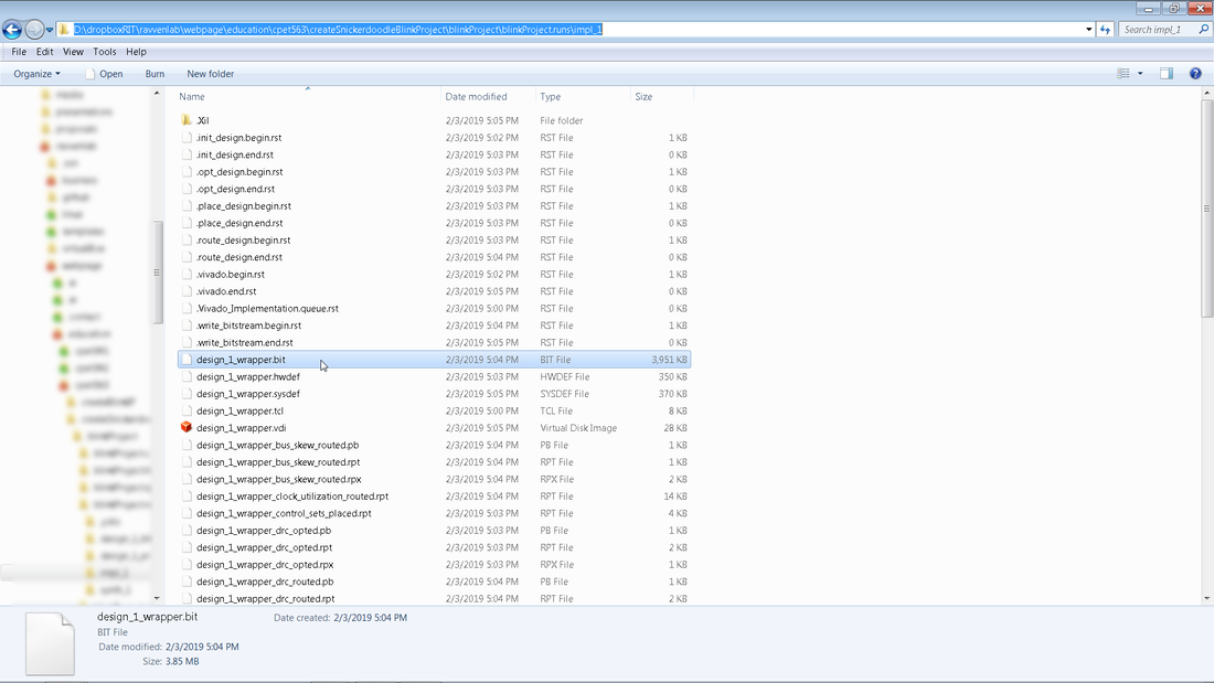
  After clicking on startScript.bat, Vivado is kicked off in batch mode [no GUI appears] and a couple minutes later a system.bit and system.bit.bin file magically show up in the project folder. These are the same files that were generated via the Vivado GUI a couple blog posts ago! I highly recommend only using the GUI for updating the block diagram as scripting is very efficient and makes for very easy versioning and code portability. Also if you do have any errors during the build process you can take a look at the vivado.jou file or open up the GUI for troubleshooting.
0 Comments
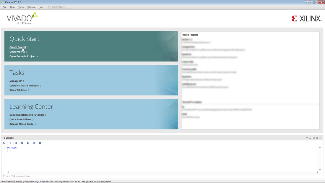
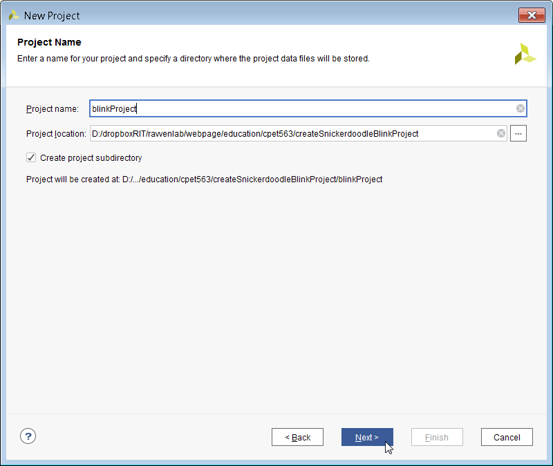
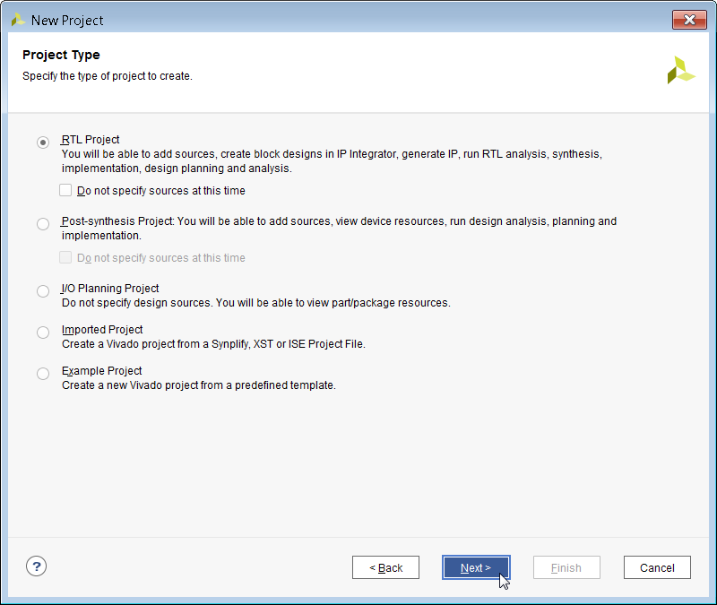
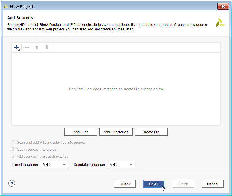
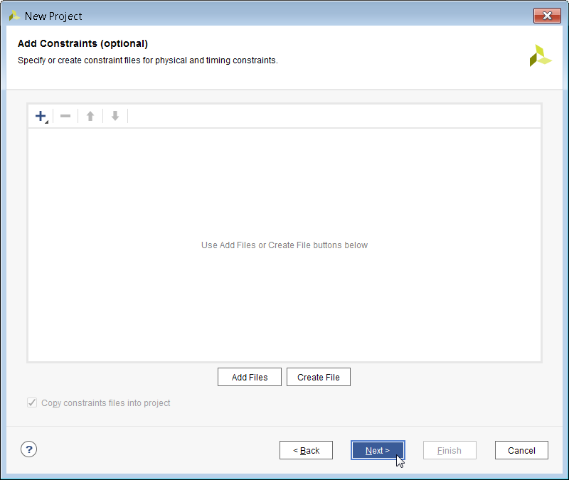
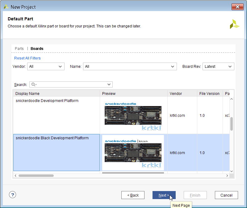
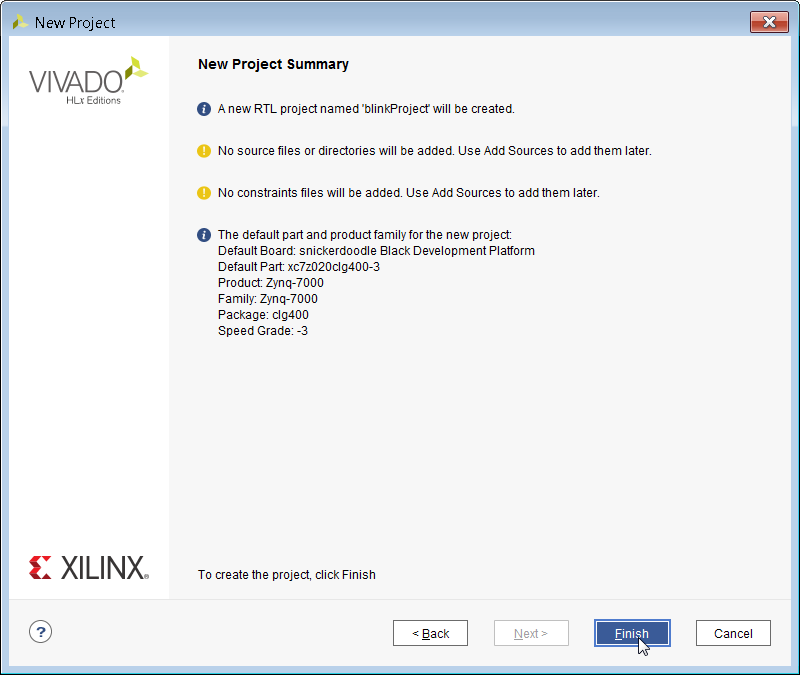
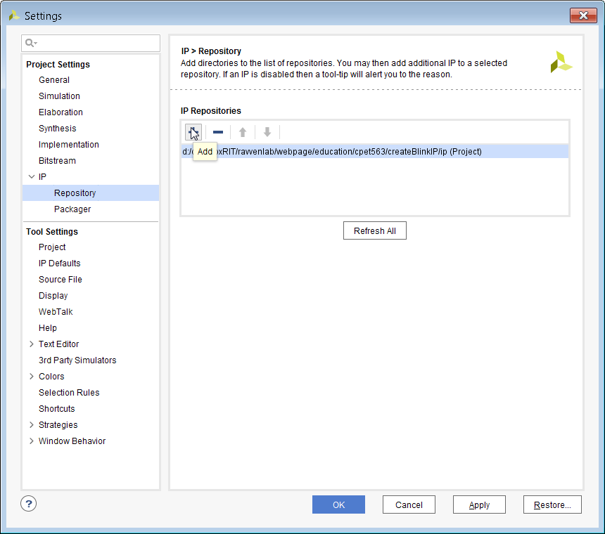
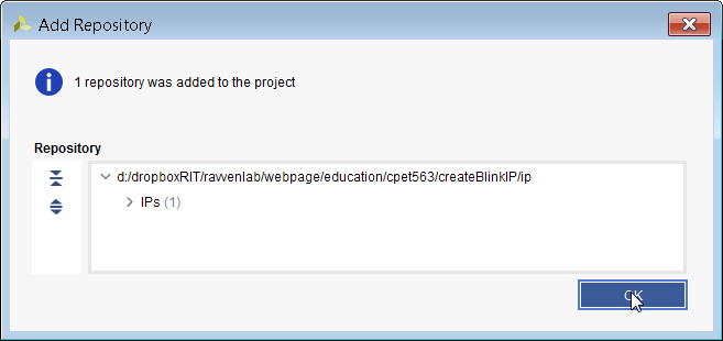
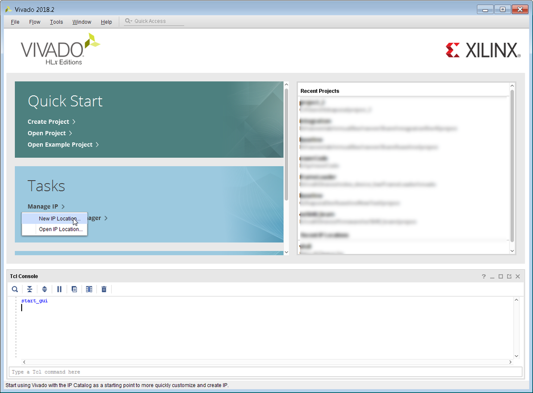
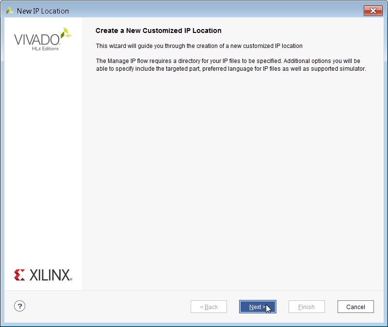
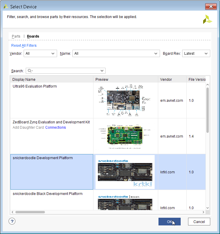
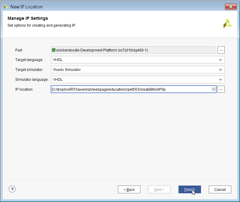
Once you have Vivado installed the next thing you will need to do is install the snickerdoodle board files. These files make it easy to create a snickerdoodle project by loading in several snickerdoode specific defaults. The board files can be downloaded or cloned here. After pulling down the files, they need to be copied into the Vivado board directory. On my computer it was: D:\xilinx\Vivado\2018.2\data\boards\board_files but it depends on where your Vivado installation is located. 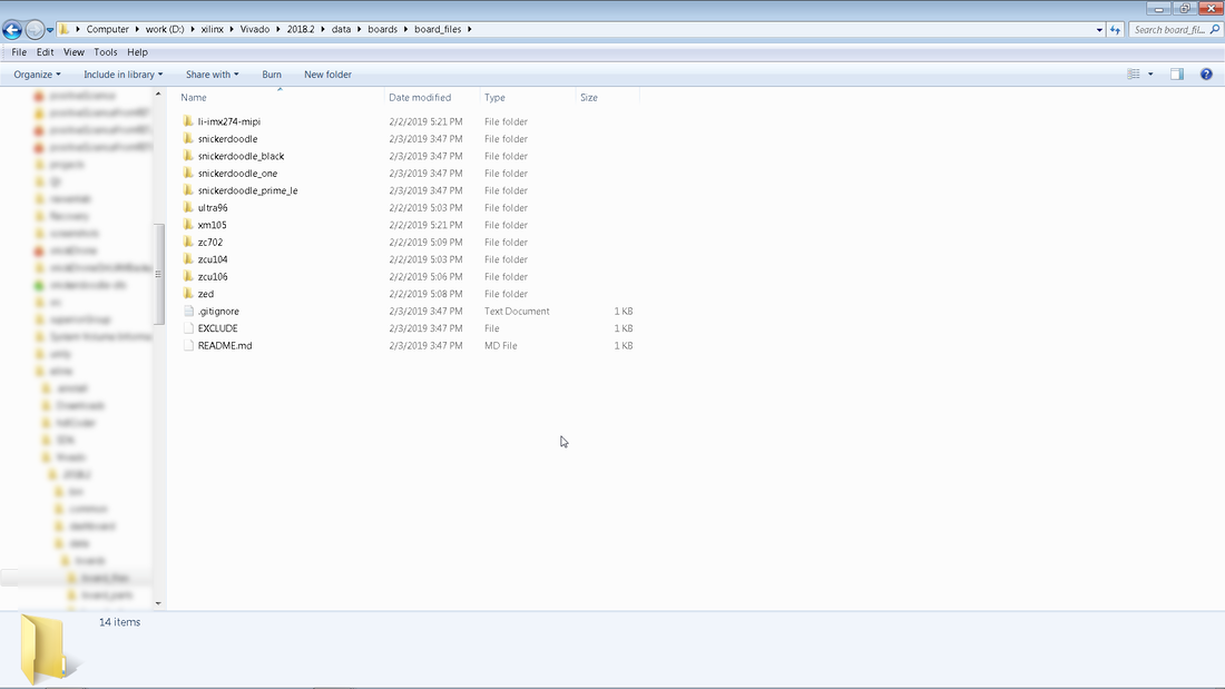 After placing the board files into the Vivado directory, start up Vivado and you should see the below screen. 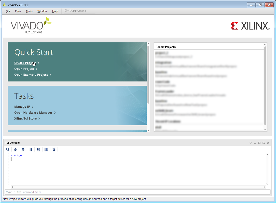 Click on Create Project and then click on Next. 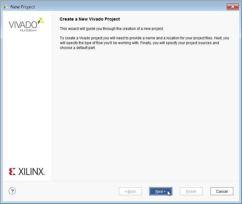 This project is just a test to see if the snickerdoodle board files are recognized by Vivado, so don't worry too much about the project location. After entering the path for the project, hit Next through the next couple of windows. 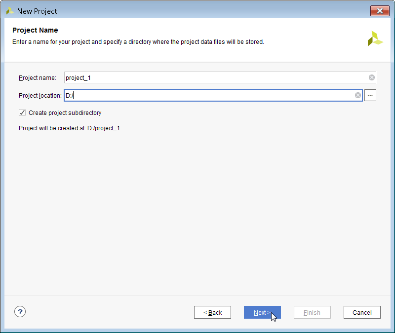 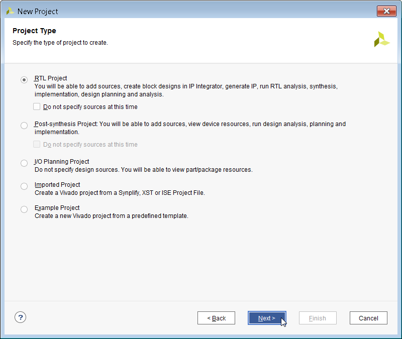 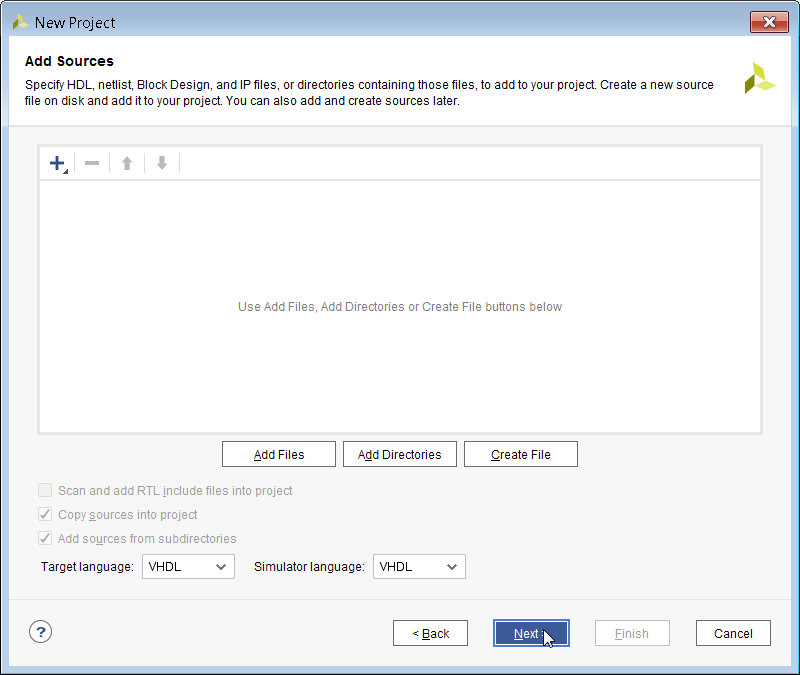 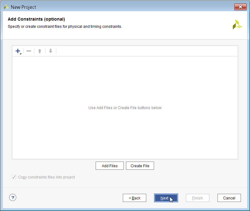 Once you arrive at the Default Part windows, click on the Boards icon in the top left and you should see the various snickerdoodle development boards show up after you scroll down a bit. Congratulations! You are ready to create your first blink project. 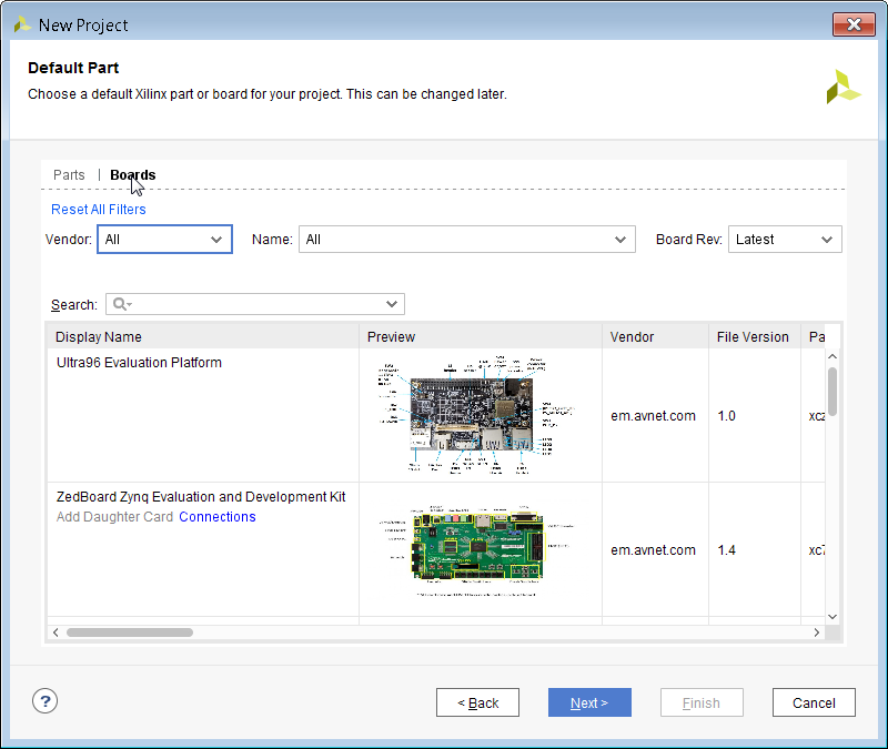 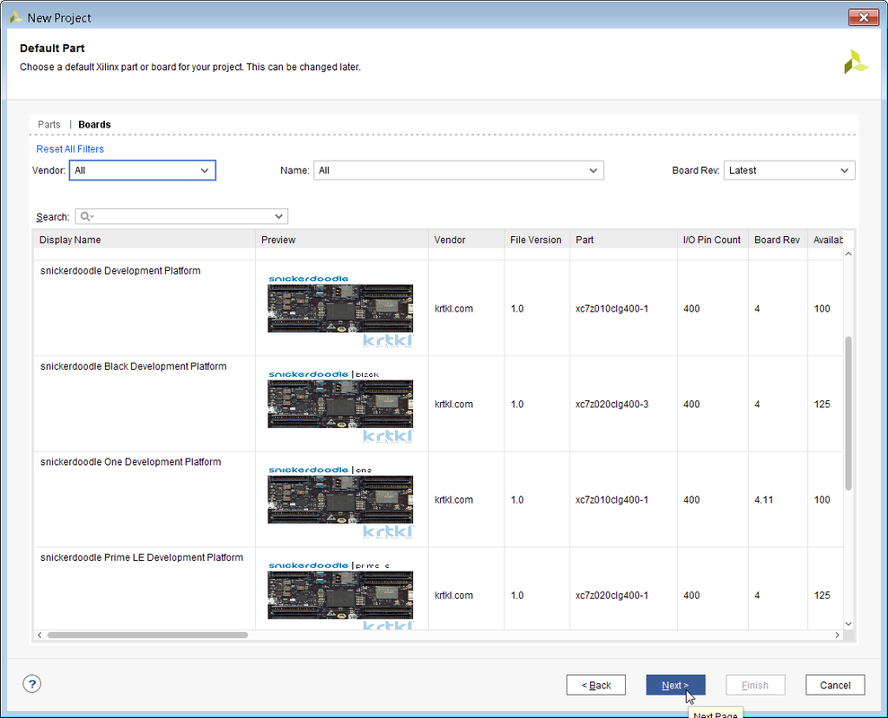
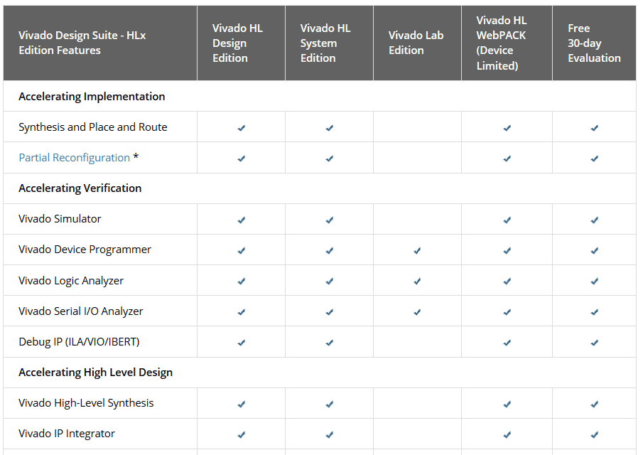
So you just got your new Snickerdoodle and you are excited to hit the ground running. Before you can make your first LED blink you need to take a step back and install the Xilinx FPGA tool ecosystem. The first step is to Download Vivado which is the tool used to create VHDL designs for the FPGA portion of the Snickerdoodle. Below is a chart that shows the different versions of Vivado, and for this tutorial I chose the WebPACK as it's free and it will work with the 7010 and 7020 chips that are on the Snickerdoodle.
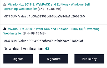
I recommend clicking on the web installer although you can pull down the entire install if you like. Once you click on the install program that is right for you, you will be asked to log in before you can pull it down. If you don't have a Xilinx account it is very easy to create a new one.
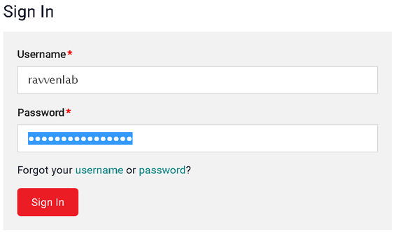
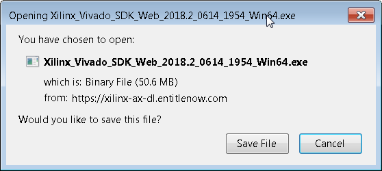
Once you log into your Xilinx account, you will be allowed to pull down the install file. Once the install file is downloaded, click on it to start the Vivado installation.
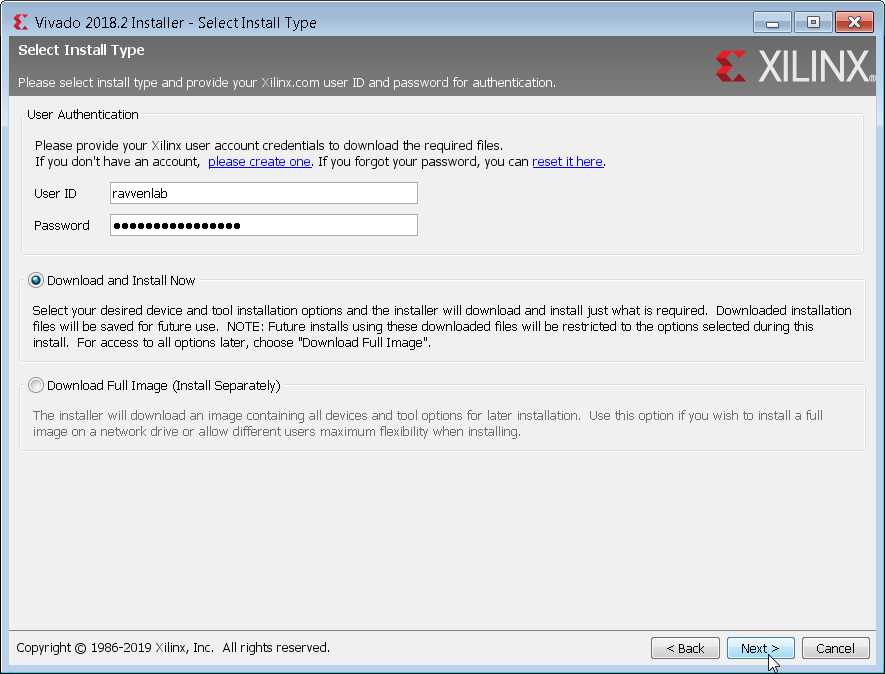
You might need to enter your Xilinx login information again, and then select the Download and Install Now option.
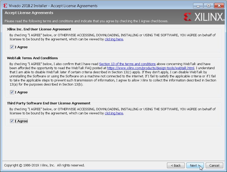
Check off all of the agreement boxes after closely reading all of the legal information..... or you can just check them as fast as you can and then hit next.
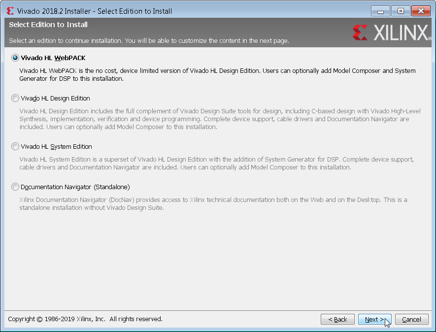
Select the Vivado HL Webpack as it is free and is compatible with all Snickerdoodles.
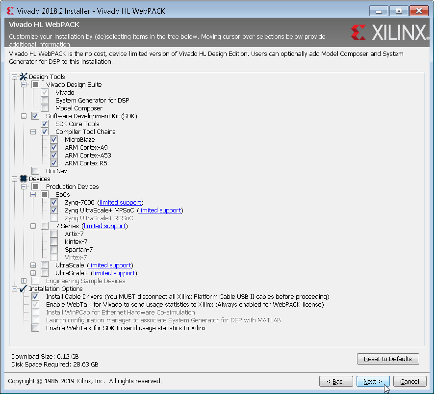
For this step I chose the smallest installation possible. If you wan to try your hand at writing bare metal C code that can run on one or both of the linux processors I would recommend checking the Software Development Kit box. Note: This will add about 10 GB to your install.
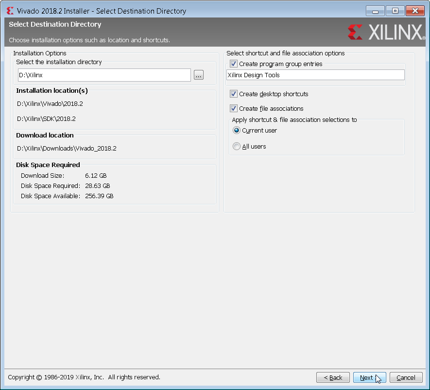
I did not use the default directory of C:\Xilinx but rather D:\Xilinx due to having more space on D:\. Note: You will have to remember where you install Vivado for when you are adding it to your system path in order to enable scripting.
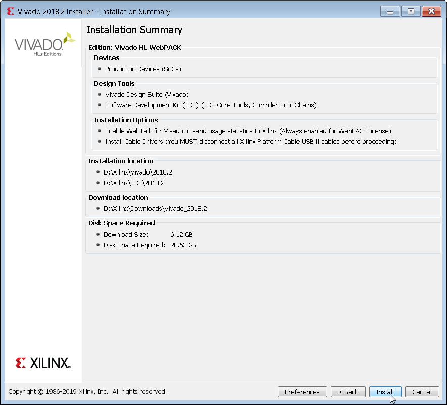
Your installation summary should look like something below.
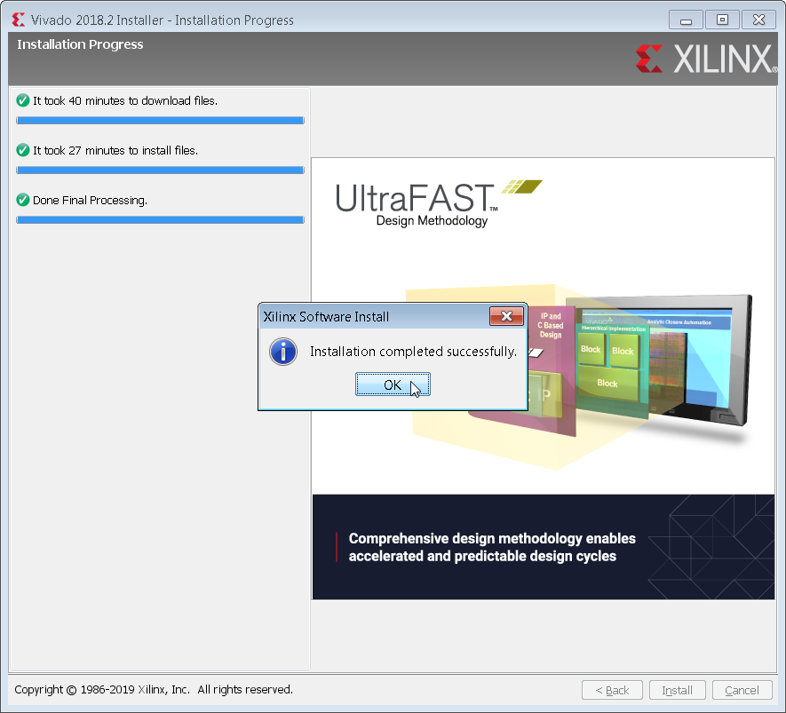
It should take around 30-40 min to pull down and install everything, but then you should get something that looks like the below screen shot. Congratulations you have just installed Vivado 2018.2.

The best way to install python, PyQt and OpenCV is to install Anaconda which contains python and PyQt4 in its site packages folder by default. One must manually install OpenCV which is covered at the end of the tutorial. Make sure to install from this link as the newer Anaconda installations have python 3 and PyQt5 which will not work as well on the embedded side of things. Once you have pulled down Anaconda from the link above click on the file to install it.
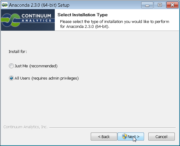
You can select whatever option you like but I typically install everything for all users.
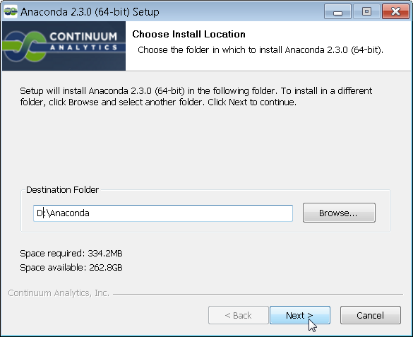
The default is C:\ however I have more space on D:\ so that is where I installed my Anaconda.
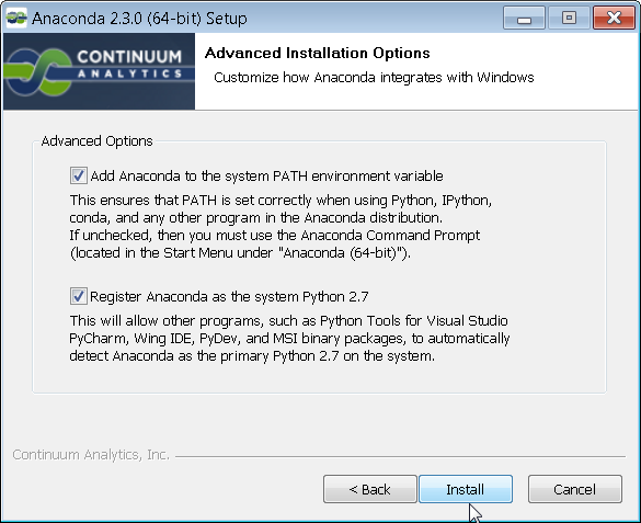
You want to make sure that the system recognizes the Anaconda python as the main python for the system in order to run code from the command prompt.
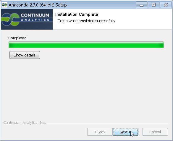
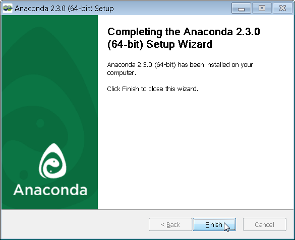
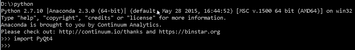
When the installation is finished you can navigate to the command prompt and type python to verify that indeed the Anaconda python is that version that comes up. If python 2.7 comes up then you have installed Anaconda correctly. Then type import PyQt4 and there should not be any errors. Congratulations, you are ready to use PyQt!
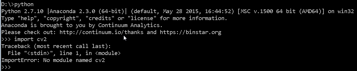
Unfortunately the default installation of Anaconda does not contain OpenCV for some reason which can be evidenced by typing in import cv2 into python as shown below.
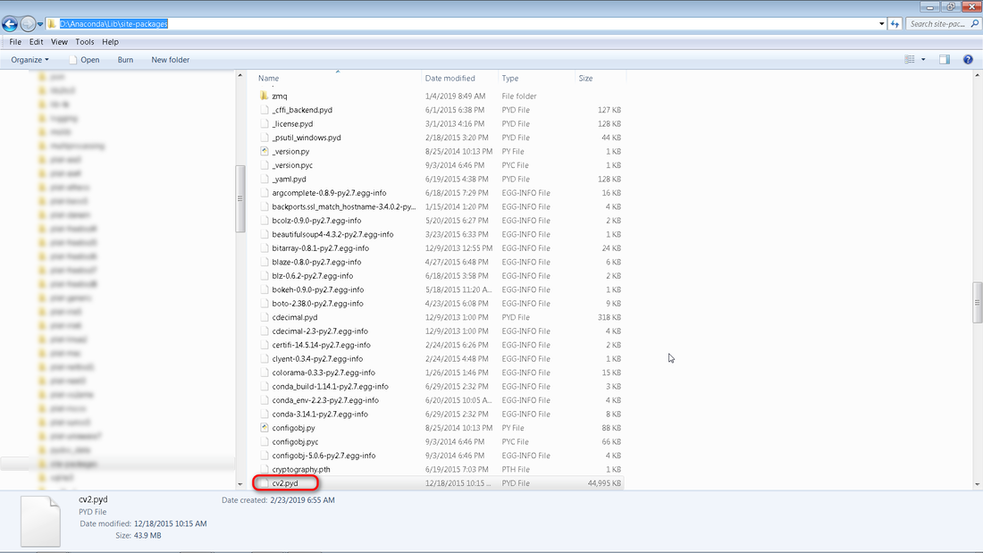
The easiest way to install OpenCV is to copy thiscv2.pyd file into the Anaconda site-packages folder. For me I had to navigate to d:\Anaconda\Lib\site-packages as shown below.
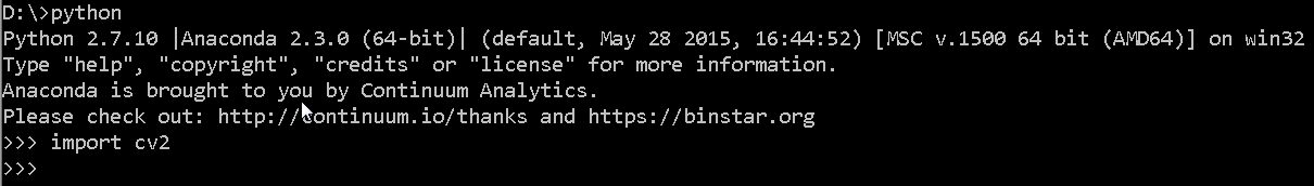
Once you have copied over the cv2.pyd file, open up a new terminal window, type python and then retry import cv2. Hopefully it returns without an error. Congratulations, you are ready to use OpenCV!
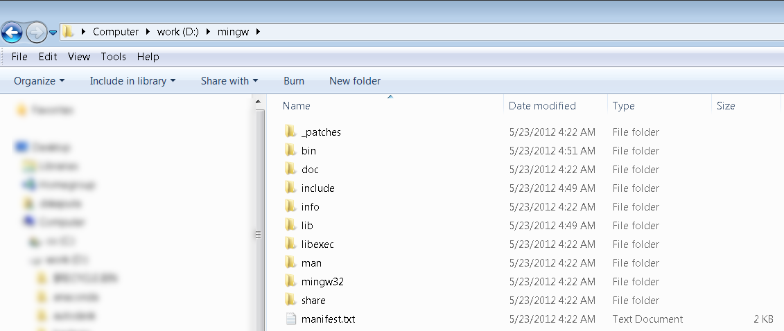
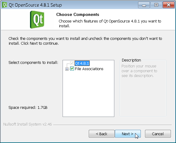
QT is a very powerful cross-platform graphics environment that can be run on both the PC as well as an embedded ARM system. This tutorial will walk you through installing QT as well as the MinGW compiler for windows. You will first need to download MinGW, Qt4, and Qt Creator. Once you have downloaded these files, unzip MinGW-gcc-4.4.0-2.7z to a folder such as D:\MinGW-gcc-4.4.0-2. You should see a folder structure like the one below.
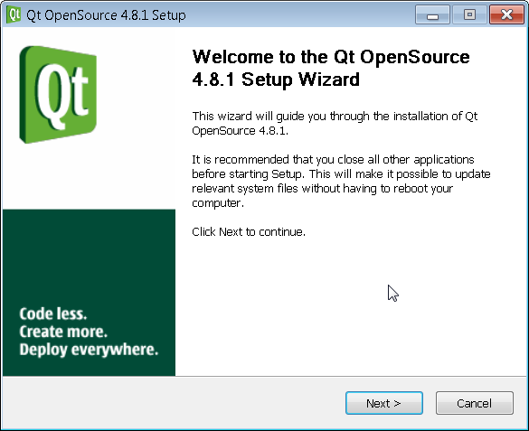
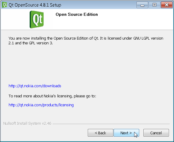
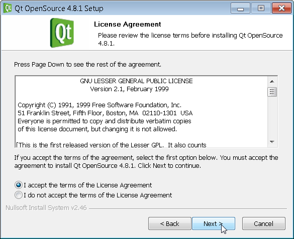
Then click on qt-win-opensource-4.8.1-mingw.exe to install QT. You can walk through the install screens as shown below.
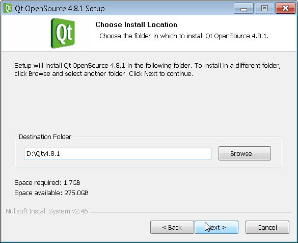
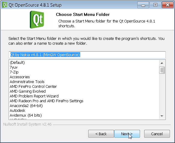
The default is C:\ however I installed on D:\ as I had more space there. You can choose to install QT wherever you like but you need to remember this location for when we add it to the system path variable later.
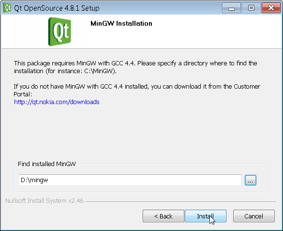
Make sure to put in the path where you previously installed MinGW from above.
De-select both check boxes and click on finish. If you leave these boxes selected I believe the examples will crash for some reason.
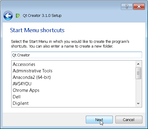
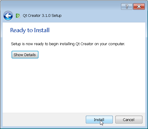
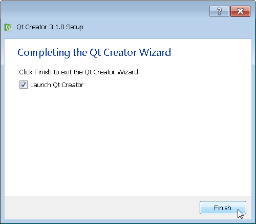
Next you should click on qt-creator-opensource-windows-x86-3.1.0.exe to install QT Creator
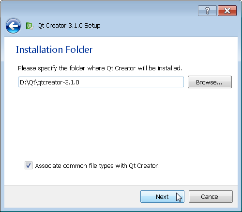
As before the default is C:\ however I chose to install it on D:\
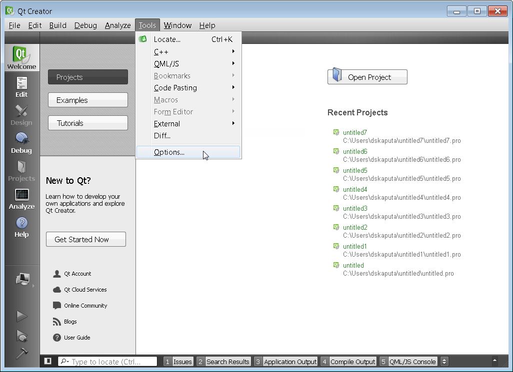
Once QT Creator is installed, the first step is to setup the compiler tool chains. This can be done via the Options menu.
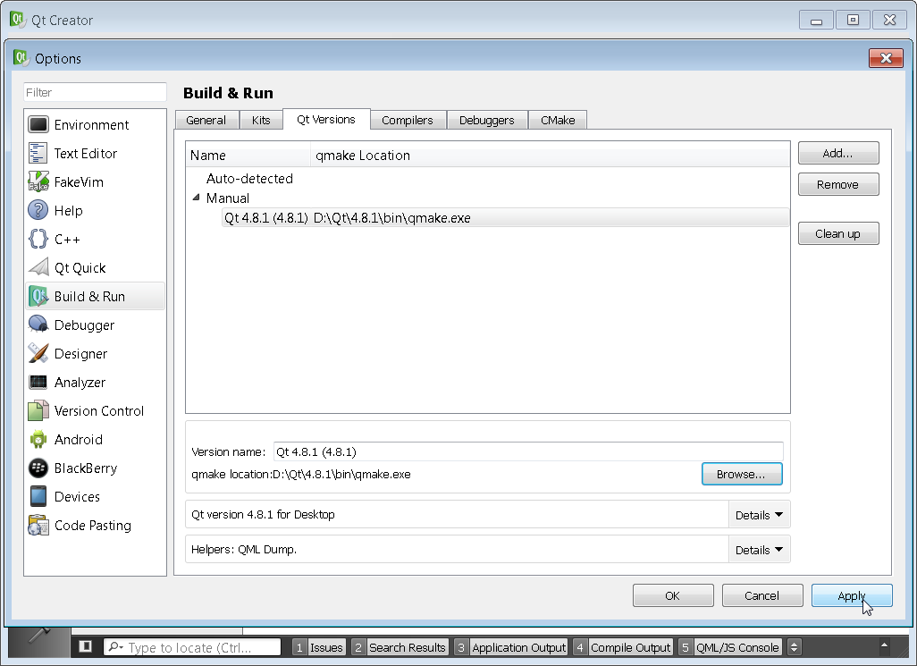
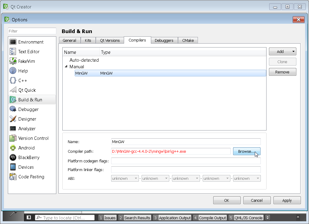
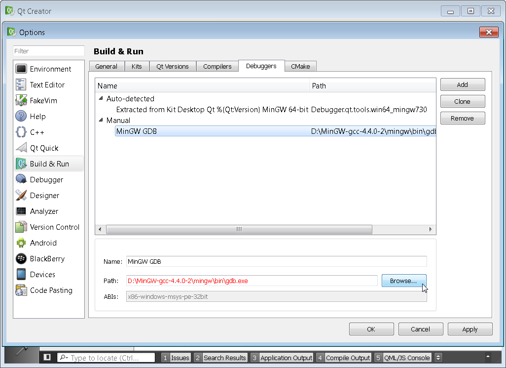
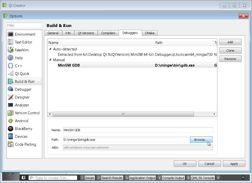
You will need to make sure that all four sections Kits, Qt Versions, Compilers, and Debuggers are configured correctly. You need to setup the Kits section last. Simply click on the various tabs browse to the proper path. If there is an error the path will typically highlight in red as shown below. The proper paths will be the location of Qt and MinGW that you had set in the steps above. This step is just telling Qt Creator where you have installed Qt and the associated compiler.
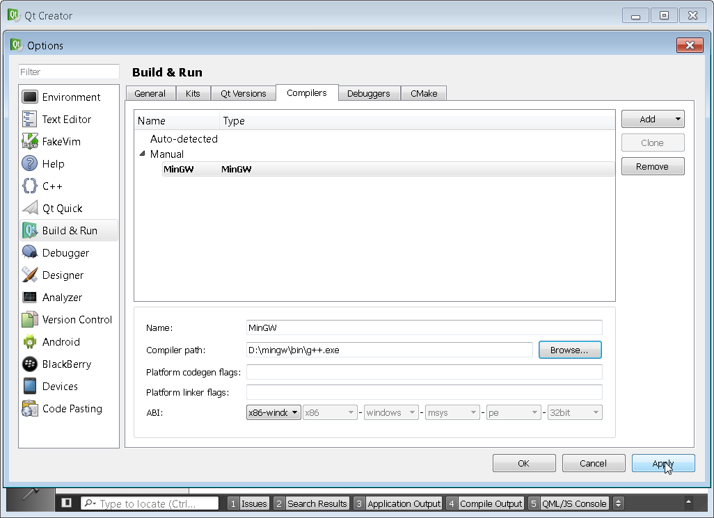
You can see that my compiler location was incorrect and I had to browse to the correct D:\mingw\bin folder for both the Compilers and Debuggers tab. Make sure to point to g++.exe and gdb.exe respectively.
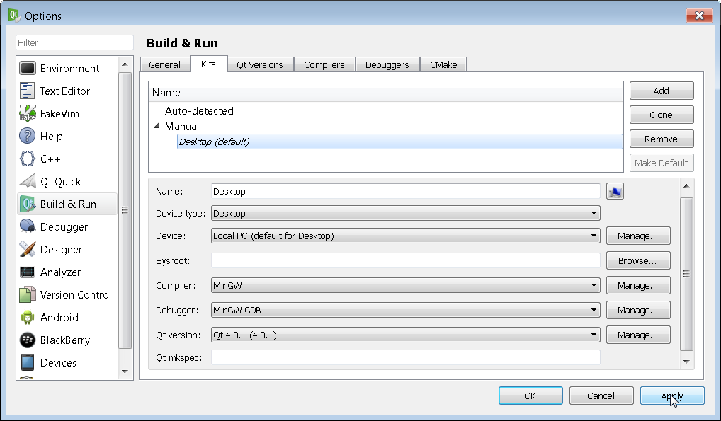
Once all of the tool chains have been setup, navigate to the Kits tab and verify that all of the fields are non-red. Then click on Apply in order to finalize the Kit.
After the kit has been finalized click on New Project.
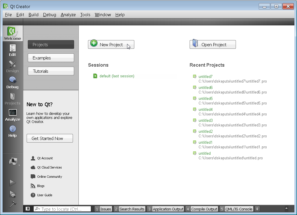
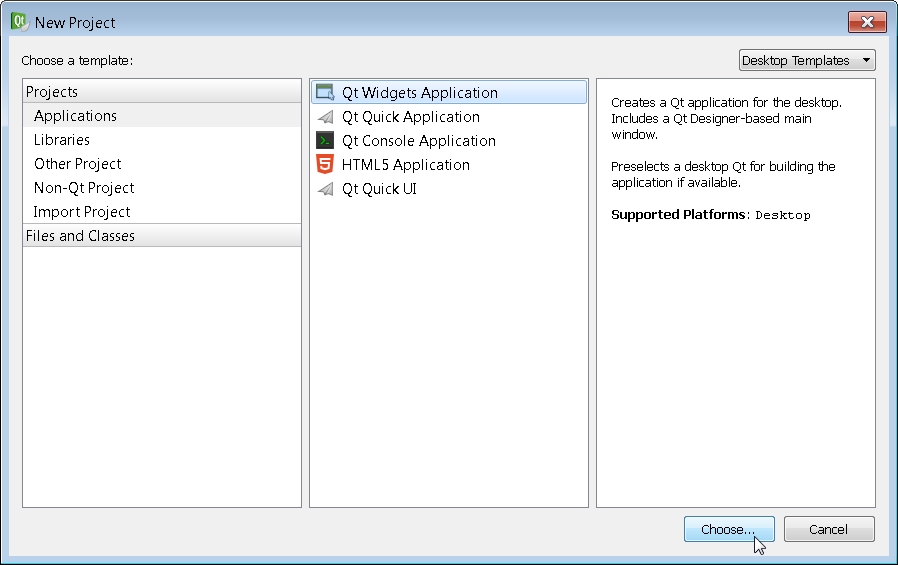
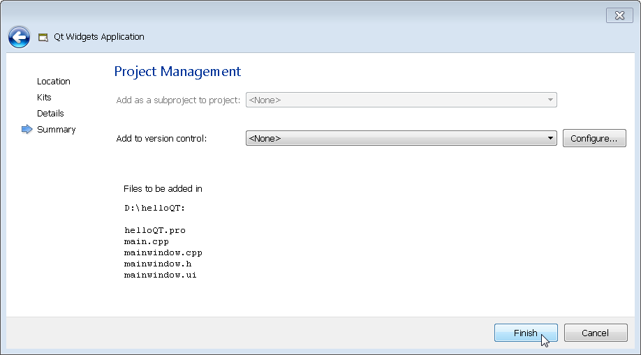
Select the Qt Widgets Application and click on Choose.
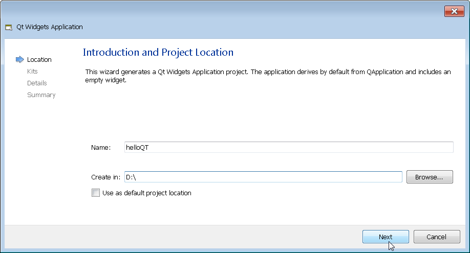
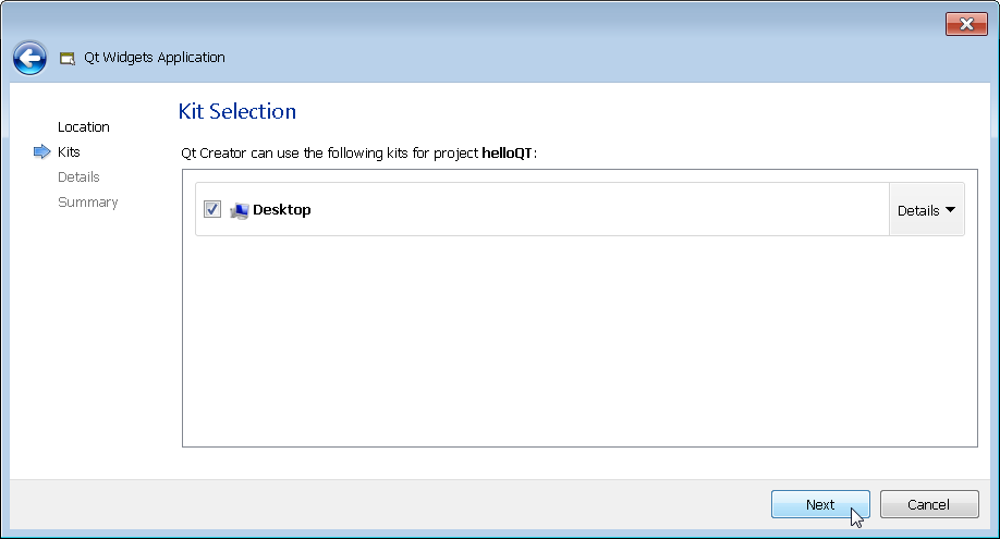
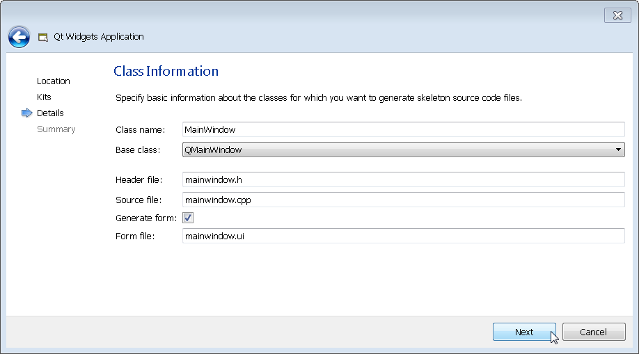
Select a project name and directory and click Next through the next several screens in order to use the defaults. Of course you can configure the project as you see fit but I typically click on Next as fast as possible.
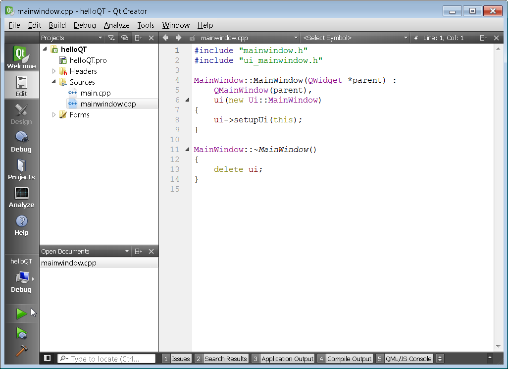
A project will be created an the mainwindow.cpp file will automatically open up. Click on the green arrow to the lower left in order to compile the project.
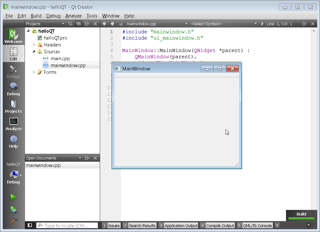
If you have all of the tool chains setup correctly you should see the program compile successfully and the Main Window should pop up.
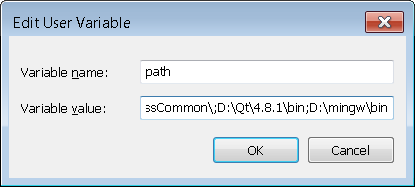
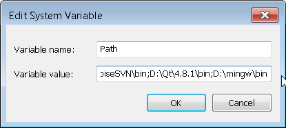
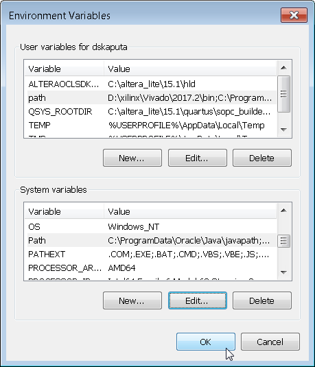
Congratulations on installing MinGW, Qt, and Qt Creator. The last step is to add them to your system path so you can execute programs from the command prompt. If you are unsure how to do this, just google "how to modify environment variable" for your specific operating system. Go into the user and system dialog boxes and edit the path variable by adding the below text to the end of the list.
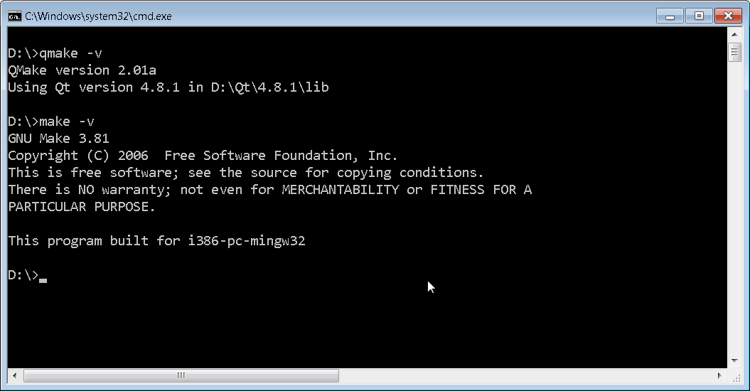
If you have successfully updated your path environment variables then when you open up a command prompt you should see the below results when you type qmake -v and make -v. Make sure that you open up a fresh command prompt after you update your environment variables. Congratulations, you are ready to play with Qt!
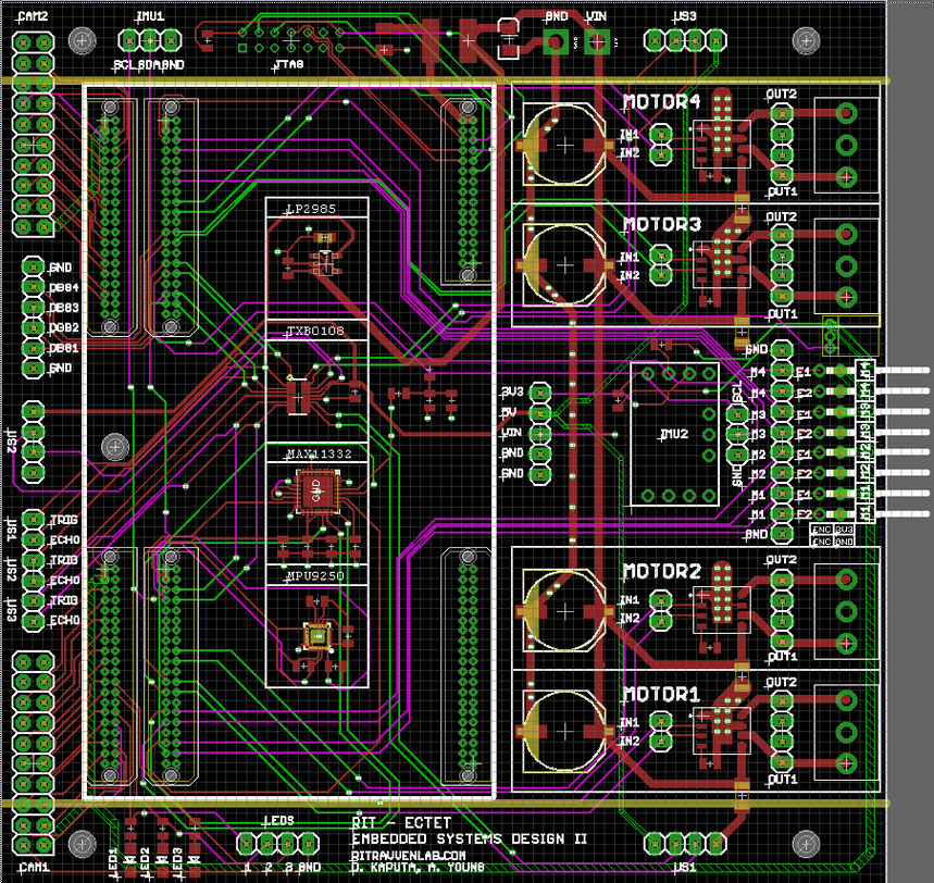
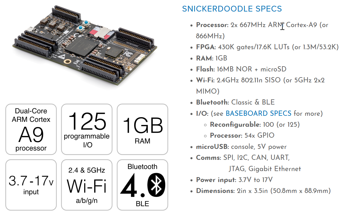
For the senior design class Embedded Systems Design II at RIT we decided to base our curriculum around the Snickerdoodle System on Module [SOM] by Krtkl. This truly amazing SOM contains the Zynq FPGA System on Chip [SOC] as well as other neat features such as integrated WiFi, rugged SD card holder, and plenty of expansion headers. The connectors-up Snickerdoodle is pictured below. Note that one can purchase Snickerdoodle with various connector configurations as well as with the 7010 or 7020 Zynq IC. 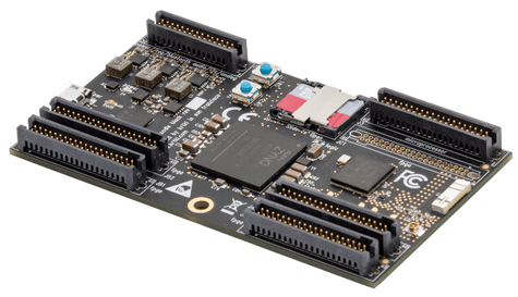 Even though the Snickerdoodle SOM is great to work with, it's always more fun when your hardware can move around. With motion in mind, our group at the Ravven lab decided to integrate the Snickerdoodle onto a rover platform. We developed the below baseboard for the Snickerdoodle to plug into that contains the following components as well as plenty of debug test points.
 For the actual rover platform we decided to use the Rover 5 which can be found here. We went with the version of the rover that has encoders, although there is also an encoderless version available. Documentation for the rover including physical dimensions can be found here. 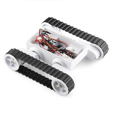 After putting it all together we arrived at the Ravven Rover pictured below! This rover has inertial measurement units [IMUs], encoders, cameras, and ultrasonic transducers which combine to make an amazing sensor suite for autonomous navigation. Another highlight of this system is that navigation algorithms can be developed in VHDL, Verilog, Java, C, Python, and any other language that can target an ARM processor. 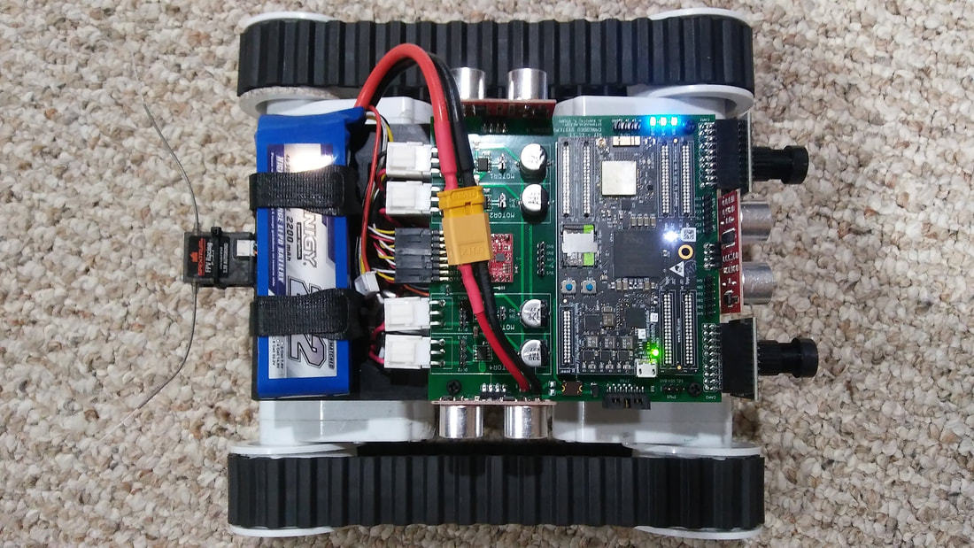 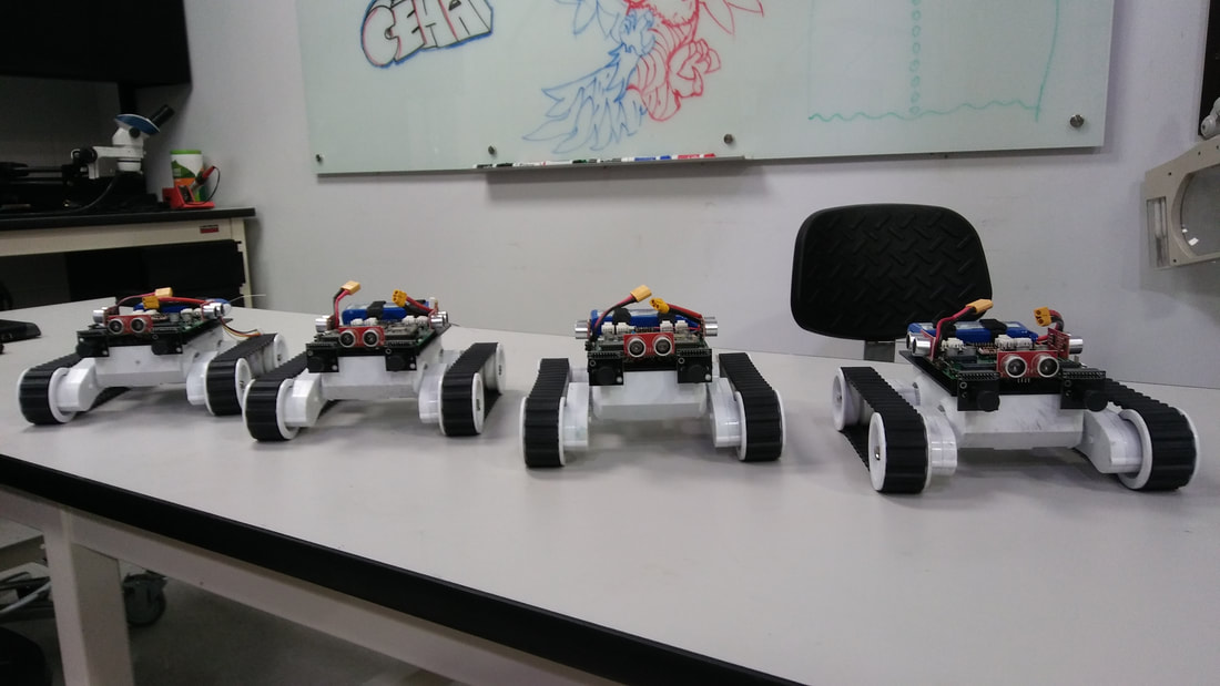 Speaking about algorithms, a pre-compiled binary is available via the Ravven lab github that contains these memory access points. One can simply pull down the system.bin file, flash the Snickerdoodle, and execute the python unit tests. 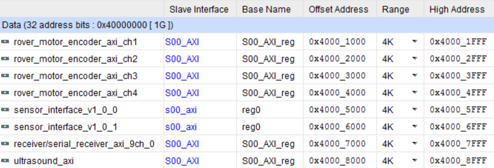 Just to prove that we actually got things working, here is a video from the Imagine RIT Festival that was held this past summer. Imagine RIT is an all ages, all day festival that features various senior projects such as this project as well as other student run clubs such as the Electric Vehicle Team [EVT] and Baja. If you are interested in being involved with this project and helping to push it forward please email me at [email protected]. We would be happy to discuss potential development and collaboration opportunities.
You may be wondering what the Snickerdoodle development board is. Check out krtkl.com to find out all about it. I have included some of its specs below. Essentially it is a super small and portable supercomputer containing an FPGA SoC as well as WiFi and Bluetooth. This tutorial will guide you through creating your very own SD card image based on the Ubuntu 16 file system.
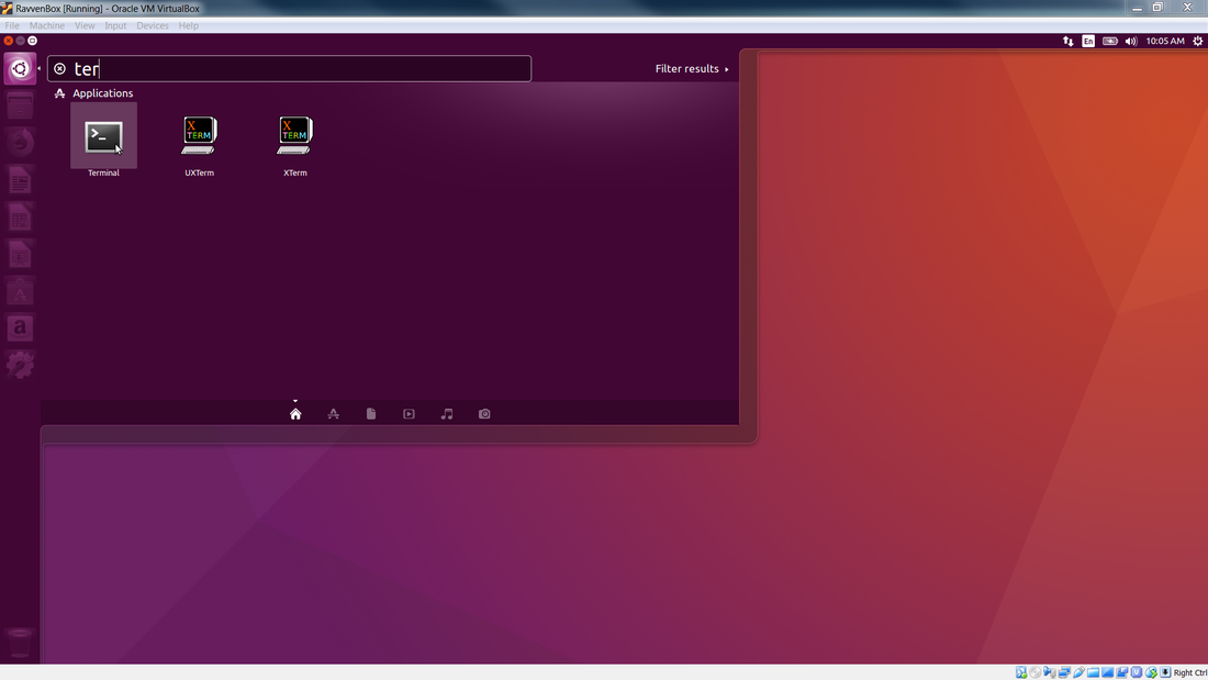
The first thing you will have to do is start up your linux virtual box which we covered here. Then open up a terminal window by first clicking on the Ubuntu symbol in the upper left, typing ter, and then clicking on the terminal icon. Then you should see the terminal open up as shown below.

Once you are at the terminal you need to become the root user by typing sudo -i and then type in your password. Once you are the root user you will need to run the below commands to install the necessary software for the SD card compilation.
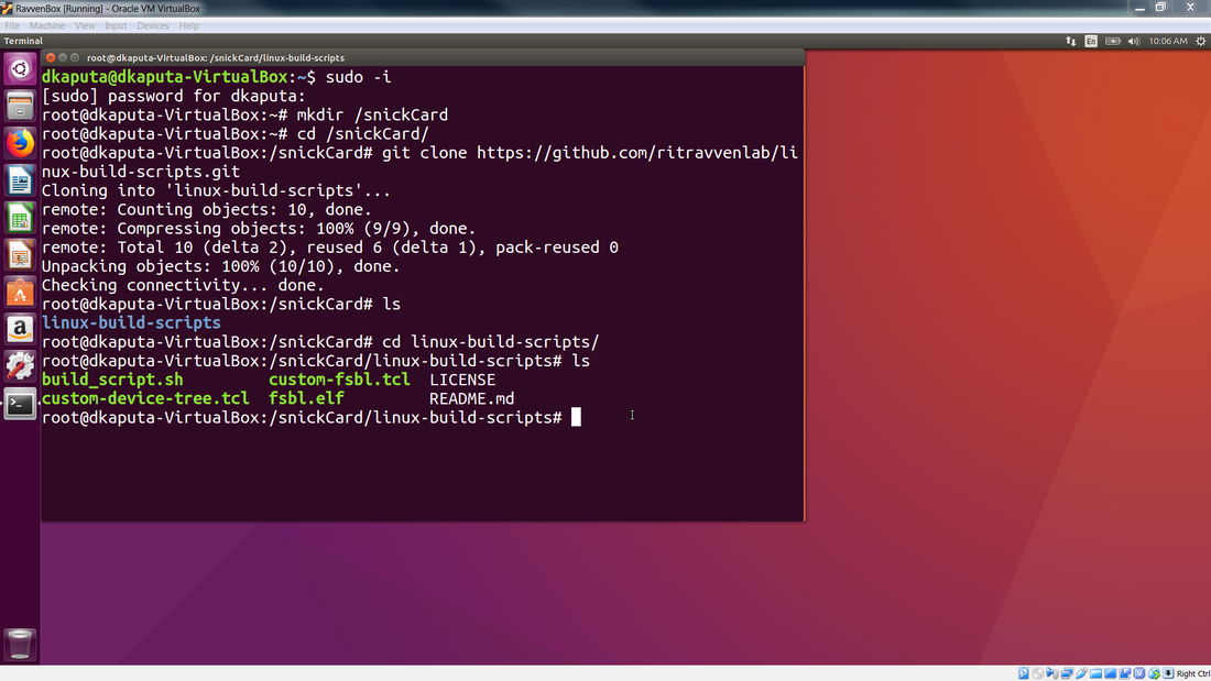
Once you have installed all of the necessary packages, create a directory where you will use as your sandbox to create the SD card. In the example I will create a directory called snickCard by typing mkdir /snickCard. The / will instruct the directory to be created at the base directory layer. You can then navigate to the directory by typing cd /snickCard. See the terminal image below. Note that I didn't pull down all the packages in the image as I already had them installed.
Once you are in your development directory you will want to clone the ritravvenlab linux build scripts repository by typing
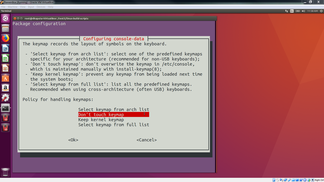
If you are feeling brave you can type ./build_script.sh all however I prefer to split things up a bit. Try the below command sequences: [also you may get prompted about keyboard configurations as shown below during the setup and I just use the defaults]
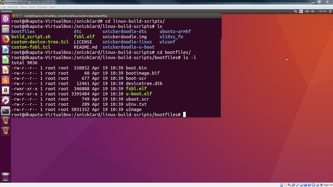
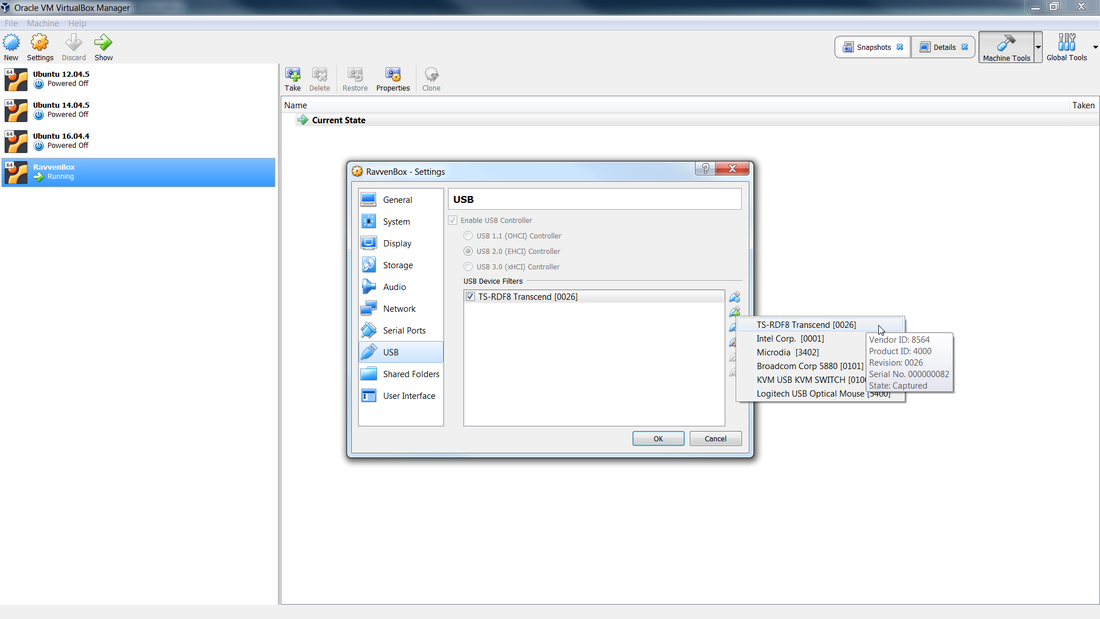
The last step is to copy that image onto your SD card. In order to do that you need to be able to see your SD card from your virtual box. This is sometimes much more difficult than it should be. I use a USB to SD converter module and plug it into my USB2 port. This is important as I have found that USB3 VM drivers are somewhat flaky. After the USB to SD card module is plugged into my USB2 port I then go to the USB tab under my VM settings and add the device as shown below. Once you do this your SD card should be able to be seen in your VM.
Now you can insert an SD card that will be flashed with the Snickerdoodle image. Be careful not to go crazy and use a 64 GB SD card as when you want to backup its image you will have a bunch of 64 GB backups taking up all of your disk space. I have found that 8 GB is a nice size which allows for roughly 4 GB of programs and gives you 4 GB for data. The first step is to unmount the SD card, and then you can dd the image over to it.
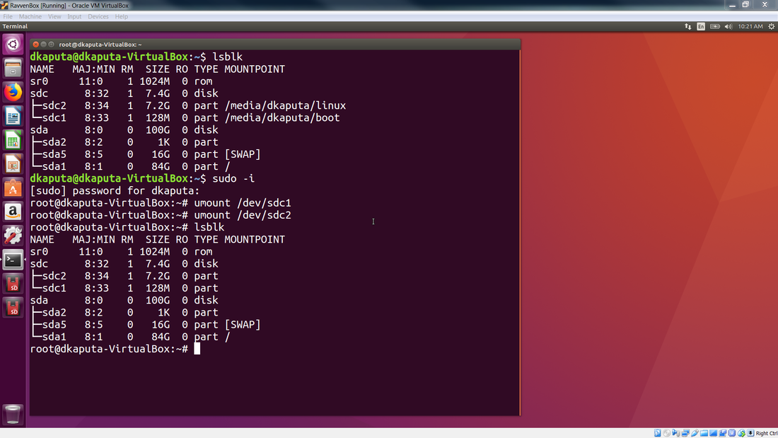
WARNING: Make sure to dd to the correct /dev/sdx location. For me it was /dev/sdc but it could be different for you.
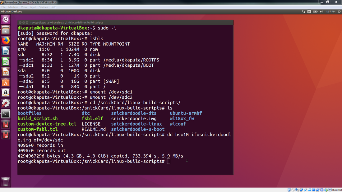
Once this completes you should have a brand new Snickerdoodle SD card!
Note that another way to write to the SD card is to use Win32 Disk Imager via a Windows machine.
|
||